Connect the Refrigerant Piping for Ceiling Cassette SystemsUpdated an hour ago
Introduction
This article explains how to connect refrigerant piping for ceiling cassette systems.
Prerequisites
- Do not install the piping until both the indoor and outdoor units have been installed.
Refrigerant Piping Specifications
Refer to these tables for the specifications of the refrigerant piping, such as the maximum piping length and drop height:
| CYT-24 Ceiling Cassette Model / Capacity (BTU/h) | 9.5K BTU | 12K BTU | 16K BTU | 23K BTU |
| Refrigerant | R-454B | |||
| Liquid Pipe Diameter | Ø 1/4 inch | |||
| Gas Pipe Diameter | Ø 3/8 inch | Ø 1/2 inch | Ø 5/8 inch | |
| Max. Length of the Piping with Standard Charge | 25 ft / 7.6 m | |||
| Max. Length Between the Indoor & Outdoor Units | 50 ft / 15.2 m | 65 ft / 19.8 m | ||
| Adjustment Refrigerant Charge (For each additional foot after 25 ft) | 0.11 oz/ft | |||
| Max. Drop Height Between the Indoor & Outdoor Units | 33 ft / 10 m | 50 ft / 15.2 m | ||
| CYB-20 Ceiling Cassette Model / Capacity (BTU/h) | 36K BTU | 48K BTU |
| Refrigerant | R-454B | |
| Liquid Pipe Diameter | Ø 3/8 inch | |
| Gas Pipe Diameter | Ø 3/4 inch | |
| Max. Length of the Piping with Standard Charge | 25 ft / 7.6 m | |
| Max. Length Between the Indoor & Outdoor Units | 250 ft / 76 m | |
| Adjustment Refrigerant Charge (For each additional foot after 25 feet) | 0.32 oz/ft | |
| Max. Drop Height Between the Indoor & Outdoor Units | 100 ft / 30.5 m | |
Notes:
- The length of the refrigerant piping will affect the performance and energy efficiency of the unit.
- Nominal efficiency is tested on units with a pipe length of 16 feet (4.9 m).
- The factory precharge supports up to 25 feet (7.6 m) of connection lineset.
- The total piping length should not be less than 10 feet (3 m).
- If the factory precharge is modified, make a note of the charge modification amount.
1. Plan the Piping Layout
Before beginning the installation, plan the refrigerant piping layout and connection.
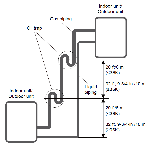
Oil Traps
If oil flows back into the outdoor unit's compressor, this might cause liquid compression or deterioration of the oil return. Oil traps in the rising gas piping can prevent this.
For systems under 36K BTU, install an oil trap every 20 feet (6 m) in the rising gas piping.
For systems equal to or more than 36K BTU, install an oil trap every 32-feet, 9-3/4 inches (10 m) in the rising gas piping.
2. Cut the Pipes
When preparing the refrigerant pipes, ensure they are cut precisely. This guarantees efficient operation and minimizes future maintenance.
1. Measure the distance between the indoor and outdoor units.
2. Use a pipe cutter to cut the pipe a little longer than the measured distance.
3. Make sure the pipe is cut at a perfect 90-degree angle. 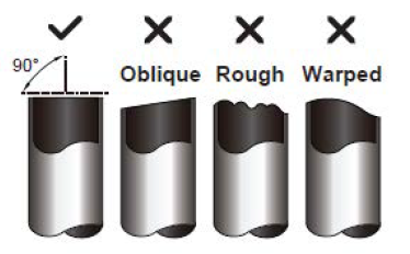
Note: Be careful not to damage, dent, or deform the pipe while cutting. This will drastically reduce the heating efficiency.
3. Remove Burrs
Burrs can compromise the airtight seal of the refrigerant piping connections and must be completely removed.
1. Hold the pipe at a downward angle to prevent burrs from falling into the pipe.
2. Use a reamer or deburring tool to remove all the burrs from the cut section of the pipe.
4. Insulate the Piping
Insulate each pipe before beginning the connection, excluding the joint sections. These will be insulated at the end of the procedure.
Insulate the gas and liquid pipes separately. Insulating them together will reduce the air conditioner's performance.
Ensure the insulation material is fitted tightly with no gaps. Do not over-tighten the insulation material. This may compress the air out of the material, causing poor insulation and early aging.
Purpose
During operation, the temperature of the gas and liquid pipes undergoes extreme overheating and over-cooling.
Proper insulation is necessary to prevent performance degradation and potential compressor burnout.
The gas pipe's temperature drops significantly during Cooling mode. If insulation is insufficient, condensation may form and lead to water damage. Conversely, the pipe becomes very hot during Heating mode, typically reaching 122-212°F (50-100°C). Ensure the insulation is properly installed to prevent burn injuries from accidental contact.
Select the Insulation Material
The insulation material must be rated for temperatures exceeding 248°F (120°C). Select the insulation materials according to local laws.
The recommended insulation casing thickness should be:
| Humidity < 80% RH | Humidity ≥ 80% RH |
| 3/8 inch (10 mm) | 5/8 inch (15 mm) |
5. Flare Pipe Ends
Proper flaring is essential to achieve an airtight seal.
1. Seal the pipe ends with PVC tape to prevent foreign materials from entering.
2. Confirm that the pipe was sheath properly with insulation material.
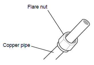
3. Place the flare nuts on both ends of the pipe. Make sure they are facing the correct direction, because it is not possible to change their direction after flaring.
4. Remove the PVC tape from the ends of the pipe when ready to perform the flaring work.
5. Clamp the flare form on the end of the pipe. 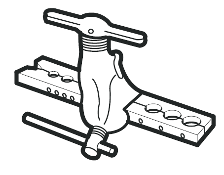
The end of the pipe must extend beyond the edge of the flare form in accordance with the dimensions shown in the tables:
Piping Extension Beyond Flare Form
| Pipe Diameter | Flare Dimension A | Flare Shape | |
| Min. | Max. | ||
| Ø 1/4 in / Ø 6.35 mm | 0.33 in / 8.4 mm | 0.34 in / 8.7 mm | 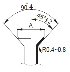 |
| Ø 3/8 in / Ø 9.52 mm | 0.52 in / 13.2 mm | 0.53 in / 13.5 mm | |
| Ø 1/2 in / Ø 12.7 mm | 0.64 in / 16.2 mm | 0.65 in / 16.5 mm | |
| Ø 5/8 in / Ø 15.9 mm | 0.76 in / 19.2 mm | 0.78 in / 19.7 mm | |
| Ø 3/4 in / Ø 19 mm | 0.91 in / 23.2 mm | 0.93 in / 23.7 mm | |
| Ø 7/4 in / Ø 22 mm | 1.04 in / 26.4 mm | 1.06 in / 26.9 mm | |
| Pipe Diameter | Torque N.m (lb.ft) | Sketch Map |
| Ø 1/4 in / Ø 6.35 mm | 18~20 (13.3~14.8) | 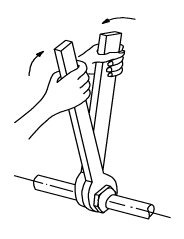 |
| Ø 3/8 in / Ø 9.52 mm | 32~39 (23.6~28.8) | |
| Ø 1/2 in / Ø 12.7 mm | 49~59 (36.1~43.5) | |
| Ø 5/8 in / Ø 15.9 mm | 57~71 (42~52.4) | |
| Ø 3/4 in / Ø 19 mm | 67~101 (49.4~74.5) | |
| Ø 7/4 in / Ø 22 mm | 85~110 (62.7~81.1) |
6. Place the flaring tool onto the form.
7. Turn the flaring tool's handle clockwise until the pipe is fully flared.
8. Remove the flaring tool and flare form, then inspect the end of the pipe for cracks and flaring.
6. Connect the Pipes
Connect the copper pipes to the indoor unit first, then connect it to the outdoor unit. Connect the low-pressure pipe, then the high-pressure pipe. Use both a spanner and torque wrench when connecting or disconnecting pipes to the unit.
Once the copper piping kit is unwound, refer to the instructions below.
Indoor Unit
1. Bring the ends of both the copper line and the indoor line together. Align the centers of the pipes that will be connected. 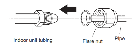
2. Remove the indoor unit piping cap and check that no debris is inside. Some gas may be heard escaping, but it is dry nitrogen to keep the lines clean.
3. Use any available leak guard or flare sealer on the piping flares. 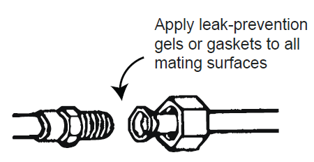
4. Attach the flare nut and tighten as much as possible by hand. 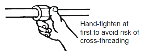
Torque correctly to the specifications found in the table below using two wrenches. Excessive force can break the flare nut or damage the refrigerant piping. Do not exceed the torque requirements.
Tightening Torque for Protection Caps & Flange Connection
| Pipe Diameter | Tightening Torque [N x m] | Tightening Torque [ft-lbf] | Corresponding Stress (Using a 20 cm Wrench) |
| Ø 1/4 in / Ø 6.35 mm | 15 - 20 | 11 - 15 | Wrist Strength |
| Ø 3/8 in / Ø 9.52 mm | 31 - 35 | 23 - 26 | Arm Strength |
| Ø 1/2 in / Ø 12.7 mm | 45 - 50 | 33 - 37 | Arm Strength |
| Ø 5/8 in / Ø 15.9 mm | 60 - 65 | 44 - 48 | Arm Strength |
| Tightening Torque [N x m] (ft-lbf) | |
| Service Port Nut | [7 - 9] (5-7) |
| Protection Caps | [25 - 30] (18-22) |
5. Repeat the process for the other copper line.
6. After connecting copper lines to the indoor unit, wrap the power cable, signal cable, and piping together with binding tape. When bundling these items, do not intertwine or cross the signal cable with any other wiring.
7. Thread this pipeline through the wall and connect it to the outdoor unit. The next section explains how to connect the pipes to the outdoor unit.
8. Optional: Attach the water receiver (supplied in the accessories box) to the indoor unit using a screw.
Outdoor Unit
1. Unscrew the cover from the packed valve side of the outdoor unit.
2. Remove the protective caps from the valve ends.
3. Align the flared pipe end with each valve and tighten the flare nut as tightly as possible by hand.
4. Use a spanner to grab the body of the valve. Do not grab the nut that seals the service valve. 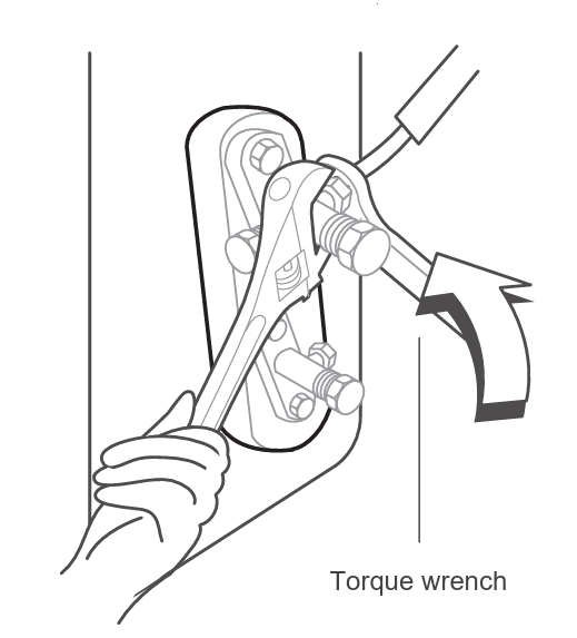
5. While firmly gripping the body of the valve, use a torque wrench to tighten the flare nut according to the correct torque values.
6. Loosen the flaring nut slightly, then tighten again.
7. Repeat the process for the remaining pipe.
8. Open the stop valves of the outdoor unit to start the flow of the refrigerant. 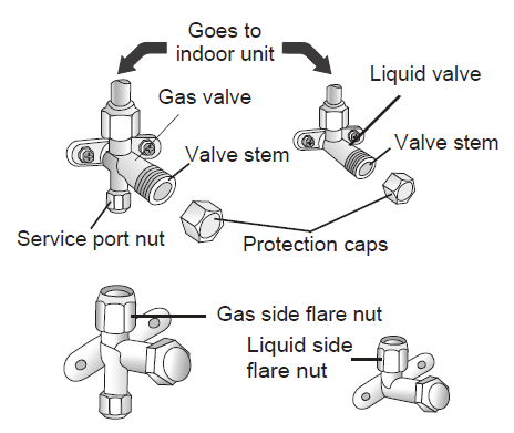
After completing the refrigerant piping connection, check for refrigerant leaks. If a leak is detected, ventilate the area immediately and evacuate the system. For more information on evacuating the refrigerant circuit, click this link.