E1, EL 01, or EL01 Error CodesUpdated 4 months ago
Introduction
The “E1”, “EL 01”, or “EL01” error codes indicate the indoor and outdoor units of the system cannot successfully communicate. This article is for discontinued Quantum series systems (WYS, CYB, RYB, UYB, and FYB).
Prerequisites
Recommended parts to prepare:
- Indoor printed circuit board (PCB)
- Outdoor printed circuit board (PCB)
- Short-circuited component
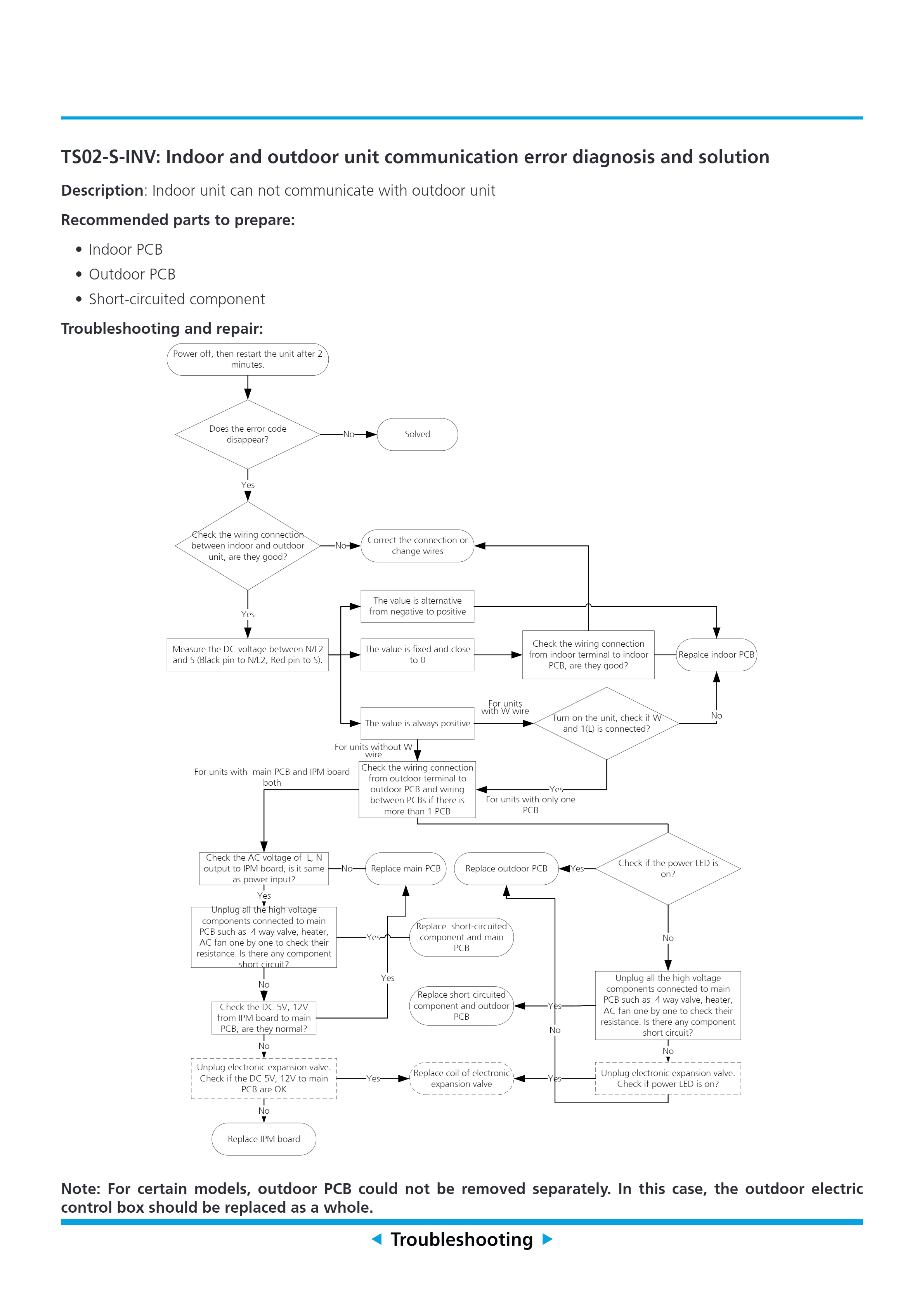
Troubleshooting
Note: An HVAC professional may be required for assistance.
The troubleshooting recommendations for new or recently installed units include:
- Check each of the communication cables. Tug on each wire to ensure they’re fastened securely. There are 8 wire ends in total – 4 on the indoor terminal block and 4 on the outdoor terminal block.
- Cut off the terminated spade head and attach bare copper.
- Check if the copper is making solid contact with the connector spades or lugs.
The troubleshooting recommendations for used units include:
- Power off the unit and restart it after 2 minutes. If the problem continues, check the wiring connection between the indoor and outdoor units.
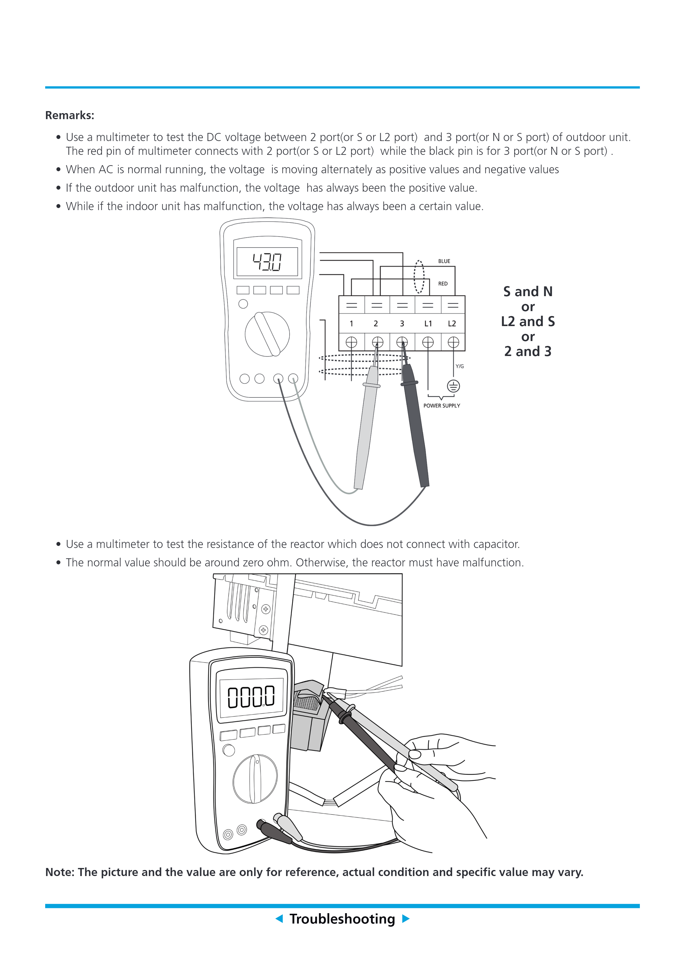
- If the wiring connection between the indoor and outdoor units are fine, test the DC voltage between N/L2 and S by using a multimeter. The red pin of the multimeter connects with 2 port (S or L2 port), while the black in is for 3 port (N or S port). Note: When an AC is running properly, the voltage is moving alternately as positive and negative values.
- If the value is alternative from negative to positive, replace the indoor PCB.
- If the value is fixed and close to 0, check the wiring connection from the indoor terminal to the indoor PCB.
- If the value is always positive, turn on the unit and check if W and 1 (L) are connected. Note: If the voltage displays a positive value, the outdoor unit has a malfunction. If the voltage holds a specific value, the indoor unit has a malfunction.
- If the wiring connection between the indoor and outdoor units is incorrect, adjust the connection or change the wires.
- Check the wiring connection from the outdoor terminal to the outdoor PCB. If there is more than 1 PCB, check the wiring between the PCBs.
The troubleshooting recommendations for units with only 1 PCB include:
- Check if the power LED is on.
- If on, replace the outdoor PCB. Note: For certain models, the outdoor PCB cannot be removed separately. In this case, the whole outdoor electric control box should be replaced.
- If not, unplug all the high voltage components connected to the main PCB to check its resistance. High-voltage components include 4-way valves, heaters, and AC fans.
- Check if there are any component short circuits.
- If there is a component short circuit, replace the short-circuited component and outdoor PCB.
- If there is not a component short circuit, unplug the electronic expansion valve.
- Check if power LED is on after unplugging the electronic expansion valve.
- If on, replace the coil of the electronic expansion valve.
The troubleshooting recommendations for used units with main PCB and IPM boards include:
- Check the AC voltage of the L, N output to the IPM board.
- If the AC voltage is the same as the power input, unplug all the high-voltage components connected to the main PCB to check its resistance.
- If the AC voltage is not the same as the power input, replace the main PCB.
- Check if there are any component short circuits.
- If there is a component short circuit, replace the short-circuited component and main PCB.
- If there is not a component short circuit, check the DC 5V, 12V from the IPM board to the main PCB.
- Check the DC 5V, 12V from the IPM board to the main PCB.
- If they appear normal, replace the main PCB.
- If not, unplug the electronic expansion valve and check if the DC 5V, 12V to the main PCB are functioning.
- Check if the DC 5V, 12V to the main PCB are functioning.
- If yes, replace the coil of the electronic expansion valve.
- If not, replace the IPM board.
Troubleshooting Diagram
Scope of Models Covered
Single-Zone Mini Split Systems | Multi-Zone and Light Commercial Mini Split Systems |
| YN009AMFI20RPD / WS009AMFI20HLD | YN020GMFI22M2E |
| YN009GMFI20RPD / WS009GMFI20HLD | YN030GMFI22M3E |
| YN012AMFI20RPD / WS012AMFI20HLD | YN040GMFI22M4E |
| YN012GMFI20RPD / WS012GMFI20HLD | YN050GMFI22M5E |
| YN018GMFI20RPD / WS018GMFI20HLD | CB009GMFILCFHD / CB012GMFILCFHD / CB018GMFILCFHD / CB024GMFILCFHD |
| YN024GMFI20RPD / WS024GMFI20HLD | RB009GMFILDFHD / RB012GMFILDFHD / RB018GMFILDFHD / RB024GMFILDFHD |
| YN030GMFI20RPD / WS030GMFI20HLD | FB012GMFILDFHE / UB018GMFILCFHD / UB024GMFILCFHD |
| YN036GMFI20RPD / WS036GMFI20HLD | WS009GMFI22HLE / WS012GMFI22HLE / WS018GMFI22HLE / WS024GMFI22HLE |
| YN009AMFI22RPE / WS009AMFI22HLE YN012AMFI22RPE / WS012AMFI22HLE | YN009GMFI22RPE / YN012GMFI22RPE / YN018GMFI22RPE / YN024GMFI22RPE |