Understand the Electrical Wiring for Vertex Ducted Central Split (DYC-18) SystemsUpdated 2 months ago
Introduction
This article explains the electrical wiring for Vertex Ducted Central Split (DYC-18) systems.
The article includes information on power supply wiring, control wiring, and grounding. The article also provides a table for electrical data.
Note: The wiring on the site must comply with the National Electric Code (C.E.C in Canada) and any applicable local regulations.
Power Supply Wiring
Ensure that there is a suitable power supply connected to the device.
Install a sufficiently-sized branch circuit breaker in a location that is in sight. In addition, make sure that the circuit breaker is easy to install.
The power supply line of the circuit must be a minimum 221°F (105°C) copper conductor. The power supply protection device can be a fuse or "HACR" type circuit breaker. For current carrying capacity, wire size, and circuit protector requirements, refer to the Electrical Data table later in the article.
High-voltage wires can pass through the tapping holes on the right, left, or top of the device.
Use the three tapped holes (7/8 inch, 1-3/8 inch, and 1-3/4 inch diameter) to connect high-voltage wires to the device.
Connect the high-voltage to the red and black wires in the control part of the air handler.
When installing an electric heater, equip the device with one or two 30-60 amp circuit breakers. These circuit breakers protect internal lines and act as disconnecting devices if short circuits occur. The circuit breaker installed in the device does not provide overcurrent protection for the power connection, so its size could be large than that of the branch circuit protection.
Note: For more detailed requirements, refer to the device rating label, wiring diagram, and electrical data.
Control Wiring
Wiring runs less than 100 feet (30.5 m) in length must use 18 AWG colored low-voltage wires. Use 16 AWG for runs with a length of more than 100 feet (30.5 m).
For the correct wiring instructions, refer to the wiring diagram on the back side of the air handler blower access panel.
After the installation, ensure that the low-voltage and high-voltage wiring are in separate conduits.
Grounding
When installing the system, ground through wires or metal conductors.
Grounding can also be achieved by connecting the grounding wire to the ground lug of the machine.
When utilizing multiple power supply circuits, each circuit needs to be connected to the grounded plate separately. The grounding plate is located at the upper right of the cabinet.
Electrical Data
Note: When used without a heat kit, match the feeder wire to the actual circuit breaker rating.
| Model | Voltage | Hertz | HP | Fan Speed | Circuit AMPS | MCA(A) | MOP(A) |
| 24K | 208/230 | 60 | 1/3 | 5 | 1.1 | 5 | 15 |
| 36K | 208/230 | 60 | 1/2 | 5 | 2.0 | 5 | 15 |
| 48K | 208/230 | 60 | 3/4 | 5 | 3.5 | 10 | 15 |
| 56K | 208/230 | 60 | 3/4 | 5 | 4.3 | 10 | 15 |
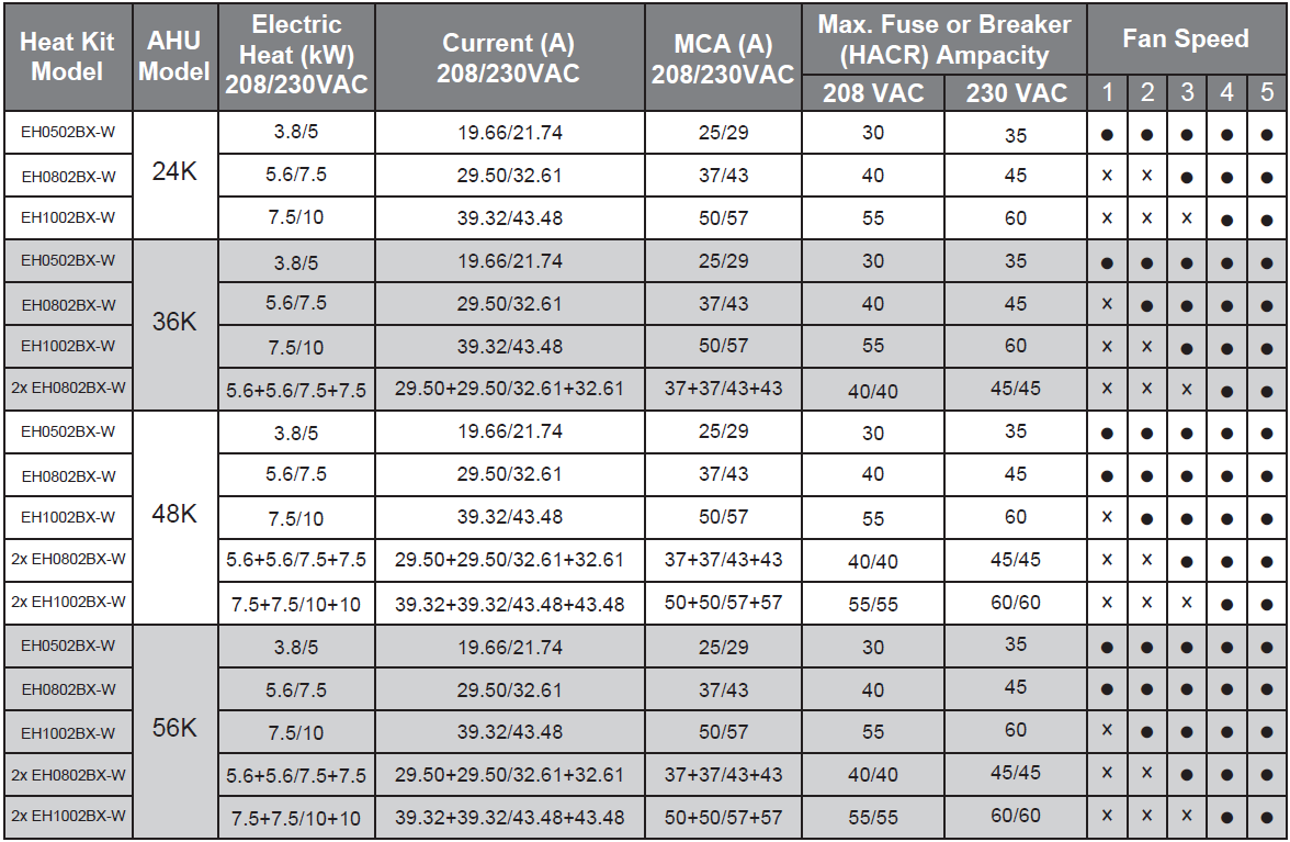
MCA/MOP Data of the Electric Heat Kit
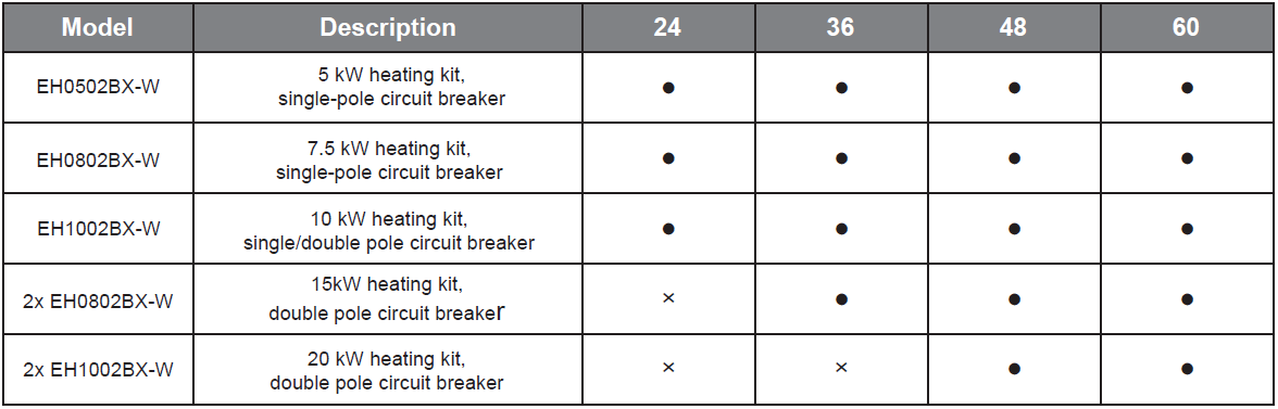
⬤ indicates availability and x indicates unavailability.
Applicable Heat Kits for AHU Multi-Position Installation
Heater Kit Accessories