Wire the Indoor Unit & Decorative Panel for Ceiling Cassette SystemsUpdated 2 months ago
Introduction
This article explains how to wire the indoor unit and decorative panel for ceiling cassette systems. It also explains how to connect the signal cable to the indoor unit.
This is the fifth step in the installation process for ceiling cassette indoor units.
This article is for the following system:
Quantum Ultra Ceiling Cassette (CYT-24)
Wire the Panel
Wire the panel's LED display board and louver swing motor to the indoor unit main control board via 10-pin and 5-pin wires.
Connect the Signal Cable
The indoor unit has three terminals (1, 2, 3) and a ground terminal (g). It is vital that the colors and numbers between the indoor and outdoor units match for each terminal. The color selection does not matter as much as matching number to number does. Do not mix up the wires between each end.
Connect the wires in accordance with the wiring diagrams, then verify that all wire strands are fully inserted and securely clamped at the terminals. All connections must be tight and free of looseness.
Consult the diagram affixed to the indoor and outdoor units respectively for specific wiring instructions. 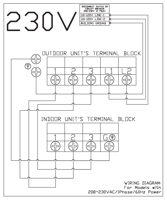
Cable Wire Specifications
| CYT-24 | 9.5K | 12K | 16K | 23K | |
| Sectional Area (AWG) | |||||
Power Supply Cable | L2 | 14 AWG | 14 AWG | 12 AWG | 12 AWG |
| L1 | |||||
 | |||||
| Connection Cable for Communication Between Indoor & Outdoor Units | 3(L) | 16 AWG | 16 AWG | 16 AWG | 16 AWG |
| 2(N) | |||||
| 1(S) | |||||
 | |||||
Consult the nameplate on the system for detailed electrical specifications.
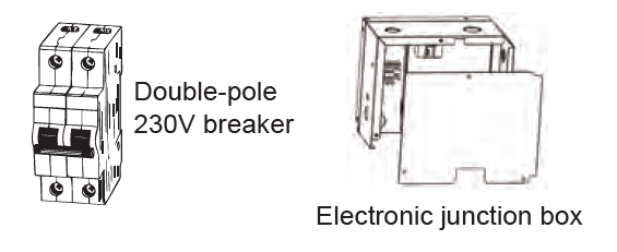
230V systems require a double-pole breaker (tandem-type will not work).