Connect the Electrical Wiring for CYB-20 Ceiling Cassette SystemsUpdated a day ago
Introduction
This article explains how to connect the electrical wiring for CYB-20 ceiling cassette systems.
Connect the outdoor unit wires before connecting the indoor unit wires.
Warnings
Before performing any electrical work, read these warnings:
General Warnings
- All wiring must comply with local and national electrical codes and regulations. A licensed electrician must install all the wiring.
- All electrical connections must be made according to the electrical connection diagram located on the panels of the indoor and outdoor units.
- If there is a serious safety issue with the power supply, stop work immediately. Explain the reasoning to the client and refuse to continue the installation until the safety issue is properly resolved.
Power Warnings
- The power voltage must be within 90-110% of the rated voltage. Insufficient power supply can cause a malfunction, electrical shock, or fire.
- Only connect the units to an individual branch circuit. Do not connect other equipment to the same power circuit.
Wiring Warnings
- Firmly connect every wire. Loose wiring can cause the terminal to overheat, resulting in product malfunction and possible fire.
- Keep the wiring away from the copper tube, as the refrigerant circuit can become extremely hot.
- Do not let wires touch or rest against the refrigerant tubing, compressor, or any moving parts.
- Do not cross the electrical wiring with the signal wiring. This may cause distortion, interference, or possibly damage to the circuit boards.
- Do not house wires of different voltages within the same wire tube. Avoid using metal wire tubes in environments prone to acid or alkali corrosion; use plastic wire tubes instead.
- Do not place wire connect joints inside the tubing. If a wire connect joint is necessary, use a connection box at the point of the joint.
Prerequisites
Complete these prerequisites before connecting the electrical wiring:
- Turn off the main power to the system. After powering off the system, wait 10 minutes or more before touching the electrical components in order to avoid electrical shock.
- Properly ground the system.
- If the unit has an auxiliary electric heater, install it at least 3-feet, 3-3/8-inches (1 m) away from any combustible materials.
- Install an external surge suppressor at the outdoor disconnect (recommended).
- If connecting power to fixed wiring, incorporate a current leakage protection switch or circuit breaker that disconnects all poles with a contact separation of at least 1/8 of an inch (3 mm). Use only an approved switch or circuit breaker.
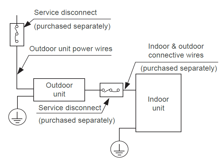
- Service Disconnect: When the air conditioner's maximum current is more than 16A, use a service disconnect or leakage protection switch with a protective device (purchase separately). When the air conditioner's maximum current is less than 16A, equip the power cord of the air conditioner with a plug (purchase separately).
Select the service disconnect as required by local, regional, and national codes. In North America, wire the appliance according to NEC and CEC requirements.
The cograph is for explanation purposes only. The machine may be slightly different. The actual shape shall prevail.
Cable Wiring Specifications
| CYB-20 | 36K | 48K |
| Sectional Area | ||
| Power Supply Cable | 14 AWG | 12 AWG |
| Connection Cable for Communication Between the Indoor and Outdoor Units | 16 AWG | 16 AWG |
Consult the nameplate on the system for detailed electrical specifications. The power wire sizes in the table assume the largest allowable fuse.
The 230V systems requires a double-pole breaker. The tandem-type will not work.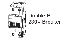
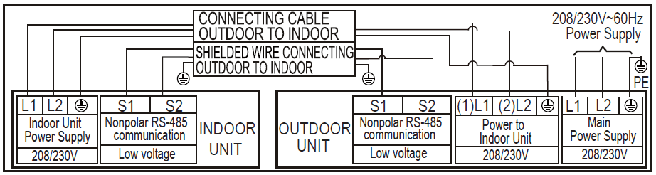
Connection Diagram
36K/48K
Connect the Wiring
Outdoor Unit Wiring
1. Prepare the cable for connection.
a) Begin by selecting the correct cable size and type according to local electrical codes and regulations.
b) The minimum circuit ampacity of the unit determines the size of the power supply cable, signal cable, fuse, and switch needed. The minimum circuit ampacity is indicated on the nameplate located on the unit's side panel. Refer to the nameplate to select the correct cable, fuse, or switch.
c) Use wire strippers to strip the rubber jacket from both ends of the signal cable to reveal 5-7/8 inches (150 mm) of the wire.
d) Strip the insulation from the ends of the cable.
e) Use a wire crimper to crimp U-lugs on the ends.
2. Remove the two screws attached on the front and side panels, then detach the panel to access the wire connections. (Outdoor Unit A).
Unscrew the electrical wiring cover and remove it (Outdoor Unit B). 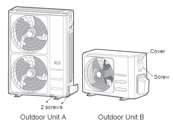
3. Connect the U-lugs to the terminals, matching the wire colors or labels with those on the terminal block. Firmly screw each U-lug to its corresponding terminal. Strictly follow the wiring diagram inside the electrical box cover when connecting the wires.
Select different colors for different wires according to relevant regulations. Ensure the wire colors for the wire colors for the outdoor unit and terminals match those used for the indoor unit.
Do not connect the power wire to the signal wire terminal. If the power and signal wires run parallel, place the wires in their own wire tube and maintain a gap of at least 11-3/4 inches (300 mm).
4. Clamp down the cable with the cable clamp. The cable must not be loose or pull on the U-lugs.
5. Insulate unused wires with electrical tape. Keep them away from any electrical or metal parts.
6. Reinstall the electrical control box's cover.
Indoor Unit Wiring
1. Prepare the cable for connection.
a) Use wire strippers to strip the rubber jacket from both ends of the signal cable to reveal 5-7/8 inches (150 mm) of the wire.
b) Strip the insulation from the ends of the cable.
c) Use a wire crimper to crimp U-lugs on the ends.
2. Open the indoor unit's front panel. Use a screwdriver to remove the electrical control box cover.
3. Thread the power and signal cables through the wire outlet.
4. Connect the U-lugs to the terminals, matching the wire colors or labels with those on the terminal block. Firmly screw each U-lug to its corresponding terminal. Refer to the serial number and wiring diagram inside the electrical box cover when connecting the wires.
5. Clamp down the cable with the cable clamp. The cable must not be loose or pull on the U-lugs.
6. Reattach the electrical control box's cover.
Magnetic Ring (if supplied with the accessories): Pass the belt through the magnetic ring's hole to attach it to the cable. 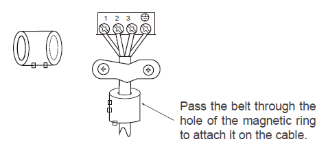
Diagrams
Super-Slim Models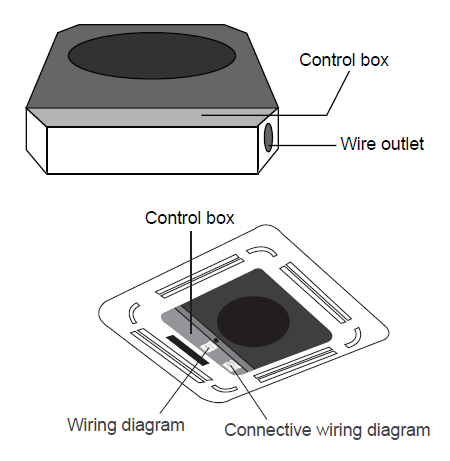
Compact Models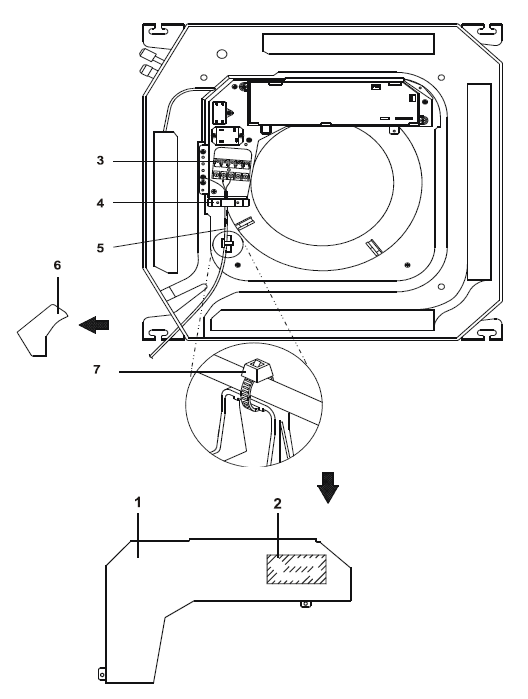
| No. | Description |
| 1 | Control box lid |
| 2 | Wiring diagram label |
| 3 | Power supply terminal block |
| 4 | Clamp for wiring |
| 5 | Wiring between the units |
| 6 | Plastic cover |
| 7 | Clamp (field supply) |