Indoor Unit Disassembly Guide: Quantum Hyperformance High-Wall SystemsUpdated 7 days ago
This article provides steps for disassembling the indoor unit of Quantum Hyperformance High-Wall (WYT-25) systems.
Steps
Before Disassembly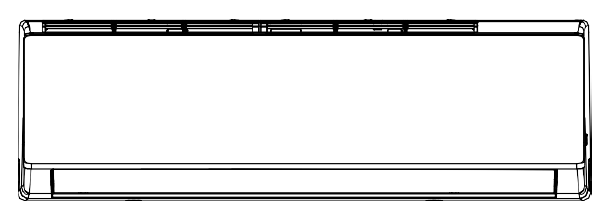
1. Remove the Front Panel and Display Box
A. Open the front panel.
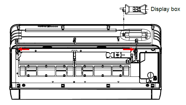
B. Remove the screw that secures the display box, and then remove the display box from the panel.
C. Release the panel hinge (indicated by the red arrows) from the middle frame, and then remove the front panel.
2. Remove the Wind Deflector and Wi-Fi Module / USB Cable
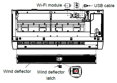
A. Slide the wind deflector latch to the right, and then remove the wind deflector. After removal, the latch remains attached to the air guide.
B. Slide the Wi-Fi module to the left to remove it.
C. Release the Wi-Fi module retaining cover from the retaining clips, and then disconnect the USB cable.
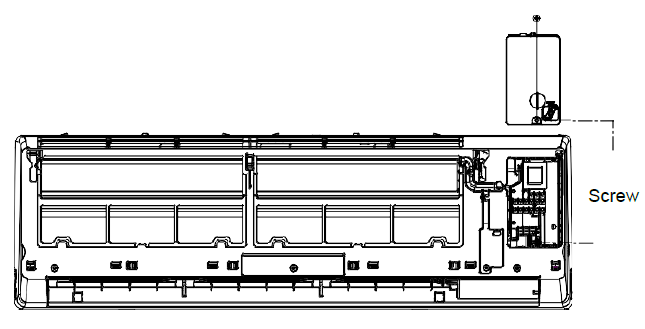
3. Remove the Electric Control Box Cover
A. Remove the screw that secures the electric control box cover, and then remove the cover.
4. Remove the Front Cover
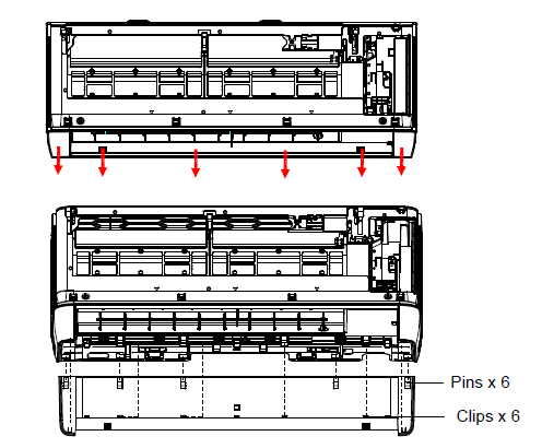
A. Press the points indicated by the red arrows to release the six clips that secure the front cover to the middle frame.
B. Rotate the front cover outward to disengage the pins that connect it to the middle frame, and then remove the front cover.
5. Remove the Sweep Blade Assembly
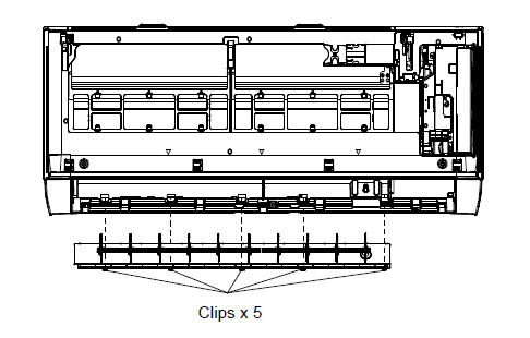
A. Release the five clips that secure the sweep blade assembly to the unit base, and then lift the assembly out.
6. Remove the Filter
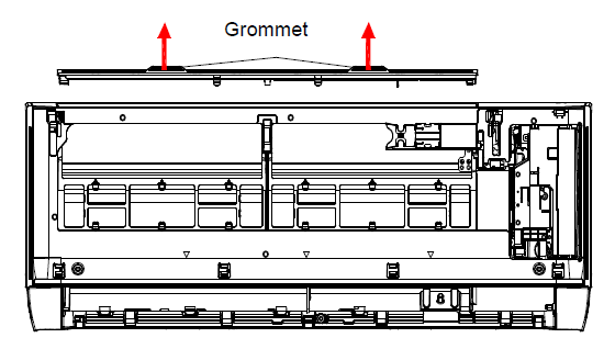
A. Pinch the top of the filter at the grommet, push it up slightly, and then remove the filter.
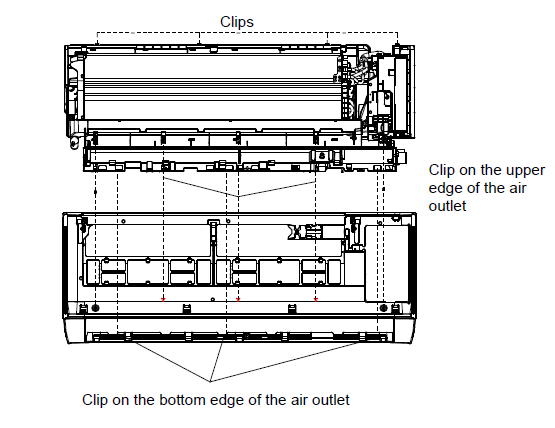
7. Remove the Middle Frame
A. Remove the two screws that secure the middle frame to the unit base.
B. Release the four clips that secure the upper part of the middle frame to the unit base.
C. Press down on the points indicated by the arrows on the middle frame to release the three clips that secure it to the upper edge of the unit base air vent.
D. Lift the middle frame out of the unit base.
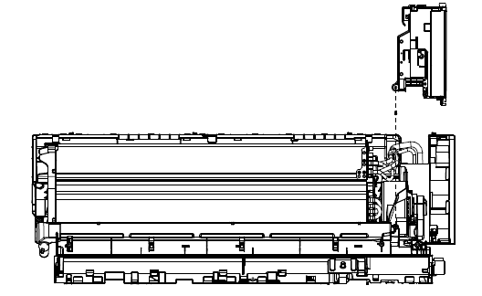
8. Remove the Electric Control Box
A. Remove the screws that secure the electric control box to the unit base.
B. Remove the electric control box.
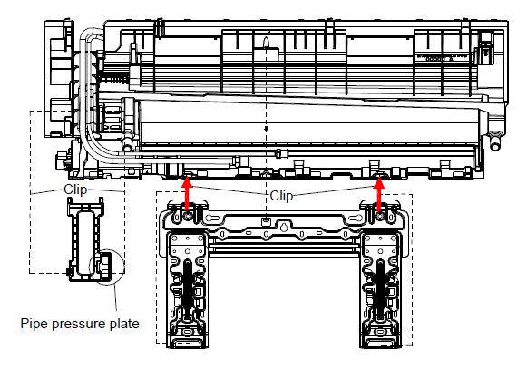
9. Remove the Wall Plate and Pipe Pressure Plate
A. Remove the screws that secure the wall plate to the unit base.
B. Press the clips on the wall plate in the direction of the arrow to release them from the unit base, and then remove the wall plate.
C. Lift the pipe pressure plate to release the clips that secure it to the unit base, and then remove the pipe pressure plate.
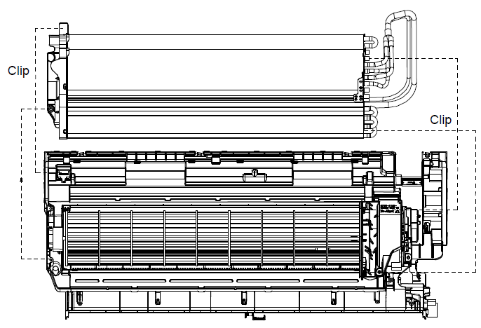
10. Remove the Evaporator
A. Remove the screws that secure the evaporator to the unit base.
B. Release the clip that secures the left side of the evaporator to the unit base, and then lift the left side. This also releases the right side of the evaporator.
C. Remove the evaporator.
11. Remove the Motor Cover
A. Remove the two screws that secure the motor cover to the unit base, and then lift the motor cover out.
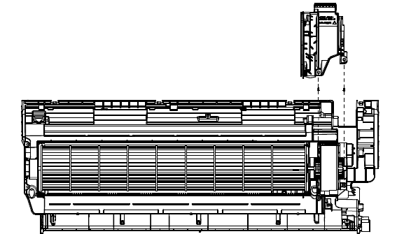
12. Remove the Cross-Flow Fan and Motor
A. Lift the cross-flow fan and cross-flow fan motor out of the unit base.
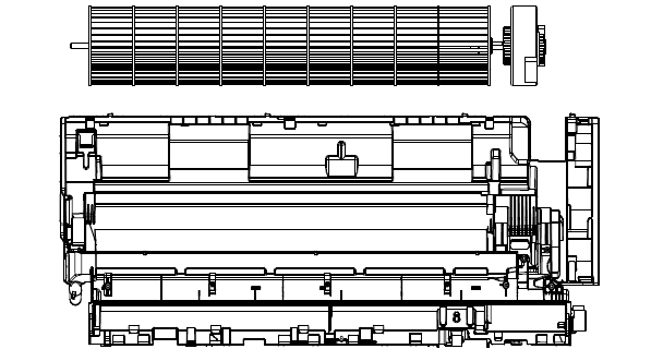
13. Separate the Cross-Flow Fan from the Motor
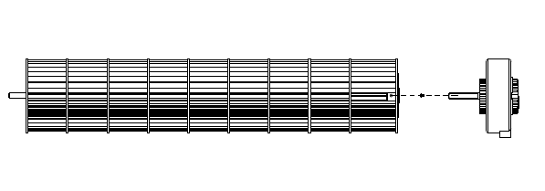
A. Remove the screw that secures the cross-flow fan to the motor shaft, and then separate the cross-flow fan from the motor.