Selecting the Installation Locations for Wall-Mounted SystemsUpdated 7 days ago
Introduction
Learn how to choose the correct installation sites for the indoor and outdoor units of wall-mounted systems.
Before starting, refer to the label on the product box to make sure that the model number of the indoor unit matches the model number of the outdoor unit.
We recommend understanding the guidelines for selecting ideal locations for the indoor and outdoor units. The following are standards intended to help select appropriate locations for the units.
This article applies for the following systems:
- Diamante Essenza High-Wall (WYT-17)
- Diamante Pro High-Wall (WYT-20)
- Quantum Ultra High-Wall (WYT-24)
- Quantum Hyperformance High-Wall (WYT-25)
Notes
- Before starting, refer to the label on the product box to make sure that the model number of the indoor unit matches the model number of the outdoor unit.
- We recommend understanding the guidelines for selecting ideal locations for the indoor and outdoor units.
- Refrain from exerting force on other parts of the unit, especially the refrigerant piping, water discharge piping, and plastic parts.
Indoor Unit
Proper installation locations for the indoor unit must ensure the following standards:
- Sufficient space for installation and maintenance.
- Sufficient space to connect the pipes and drainpipe.
- No direct radiation from heaters.
- The air inlet and outlet are not blocked.
- The airflow can fill the entire room.
- The ceiling is horizontal and its structure can sustain the indoor unit's weight.
Do not install the indoor unit in the following locations:
- Areas with oil drilling or fracking.
- Coastal areas with high salt content in the air.
- Areas with caustic gases in the air, such as near hot springs.
- Areas that experience power fluctuations, such as factories.
- Enclosed spaces, such as cabinets.
- Kitchens that use natural gas.
- Areas with strong electromagnetic waves.
- Areas that store flammable materials or gas.
- Rooms with high humidity, such as bathrooms or laundry rooms.
Height & Length Restrictions:
Select the positions of both units before starting the installation. Follow the height and length restrictions.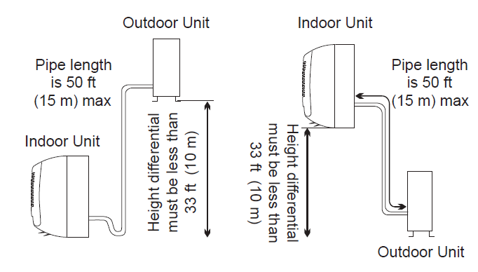
| Diamante Essenza (WYT-17) | |||
| WYT012ALUI17RL | WYT012GLUI17RL | WYT018GLUI17RL | |
| Max. Allowable Length | 50 feet / 15.2 m | 50 feet / 15.2 m | 50 feet / 15.2 m |
| Max. Allowable Vertical Run | 33 feet / 10 m | 33 feet / 10 m | 33 feet / 10 m |
| WYT024GLUI17RL | WYT036GLUI17RL | |
| Max. Allowable Length | 65 feet / 19.8 m | 100 feet / 30.5 m |
| Max. Allowable Vertical Run | 50 feet / 15.2 m | 65 feet / 19.8 m |
| Diamante Pro (WYT-20) | |||
| WYT009ALSI20RL | WYT009GLSI20RL | WYT012ALSI20RL | |
| Max. Allowable Length | 50 feet / 15.2 m | 50 feet / 15.2 m | 50 feet / 15.2 m |
| Max. Allowable Vertical Run | 33 feet / 10 m | 33 feet / 10 m | 33 feet / 10 m |
| WYT012GLSI20RL | WYT018GLSI20RL | WYT024GLSI20RL | |
| Max. Allowable Length | 50 feet / 15.2 m | 65 feet / 19.8 m | 65 feet / 19.8 m |
| Max. Allowable Vertical Run | 33 feet / 10 m | 50 feet / 15.2 m | 50 feet / 15.2 m |
| WYT030GLSI20RL | WYT036GLSI20RL | |
| Max. Allowable Length | 100 feet / 30.5 m | 100 feet / 30.5 m |
| Max. Allowable Vertical Run | 65 feet / 19.8 m | 65 feet / 19.8 m |
| Quantum Ultra (WYT-24) | |||
| WYT009ALSI24RL | WYT009GLSI24RL | WYT012ALSI24RL | |
| Max. Allowable Length | 50 feet / 15.2 m | 50 feet / 15.2 m | 50 feet / 15.2 m |
| Max. Allowable Vertical Run | 33 feet / 10 m | 33 feet / 10 m | 33 feet / 10 m |
| WYT012GLSI24RL | WYT018GLSI24RL | WYT024GLSI24RL | |
| Max. Allowable Length | 50 feet / 15.2 m | 65 feet / 19.8 m | 65 feet / 19.8 m |
| Max. Allowable Vertical Run | 33 feet / 10 m | 50 feet / 15.2 m | 50 feet / 15.2 m |
| Quantum Hyperformance (WYT-25) | |||
| WYT009GLSI25RH | WYT012GLSI25RH | WYT018GLSI25RH | |
| Max. Allowable Length | 50 feet / 15.2 m | 50 feet / 15.2 m | 65 feet / 19.8 m |
| Max. Allowable Vertical Run | 33 feet / 10 m | 33 feet / 10 m | 50 feet / 15.2 m |
| WYT024GLSI25RH | |
| Max. Allowable Length | 65 feet / 19.8 m |
| Max. Allowable Vertical Run | 50 feet / 15.2 m |
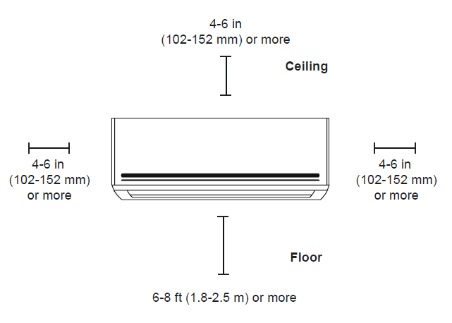
Install the indoor unit so that its bottom is at least 6 feet (1.8 m) above the floor. Ensure adequate space above the air handler for return airflow — ideally 8 inches (203 mm), but at least 4 to 6 inches (102–152 mm).
Outdoor Unit
Proper installation locations for the outdoor unit must ensure the following standards:
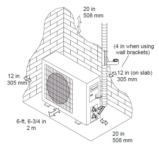
- The installation's spatial requirements shown in the illustration are met.
- The location is solid enough to support the unit and prevent vibration.
- Sufficient air circulation and ventilation.
- Noise from the unit will not disturb other people.
- The location is protected against prolonged exposure to direct sunlight or precipitation.
- The location is protected against ice buildup and coil damage during snowfall.
Do not install the indoor unit in the following locations:
- Near an obstacle that will block air inlets and outlets.
- Near public streets, crowded areas, or places where noise from the unit will disturb others.
- Near animals or plants that will be harmed by hot air discharge.
- Near any source of combustible gas.
- A location that is exposed to large amounts of dust.
- A location exposed to an excessive amount of salty air.
Special considerations for extreme weather:
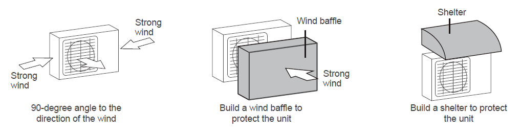
- If the outdoor unit is exposed to strong wind: Install the unit so that the air outlet fan is at a 90-degree angle to the wind direction. If necessary, build a barrier in front of the unit to protect it from extremely strong winds.
- If the outdoor unit is frequently exposed to heavy rain or snow: Build a shelter above the unit to protect it from rain or snow, ensuring the airflow is not obstructed.
- If the outdoor unit is frequently exposed to salty air (seaside): Use an outdoor unit specifically designed for corrosion resistance.