Front Panel Display for Quantum Ultra Floor-Ceiling Flex SystemsUpdated a month ago
Introduction
This article explains the front panel display layout for Quantum Ultra Floor-Ceiling Flex (UYT-24) systems.
Front Panel Display Layout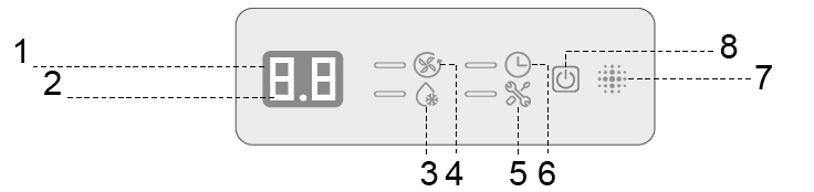
| No. | LED Icon | Symbol | Description |
|---|---|---|---|
| 1 | Signal Receptor |  | Receives signals from the handheld remote controller |
| 2 | Digital Display |  | Display temperature settings, error codes, and operational status |
| 3 | Defrost Indicator |  | Indicates that the unit is either in defrost mode or preheating |
| 4 | Operation Light |  | Indicates that the system is operating normally |
| 5 | Alert Indicator |  | Illuminates to indicate a system fault or abnormal condition |
| 6 | Timer Indicator |  | Shows that a timer function has been activated |
| 7 | Tone Emitter |  | Emits confirmation tones when receiving command signals |
| 8 | Manual Button |  | Manually powers the unit on or off without using the remote |
Notes:
- The shape and positions of the switches and indicators may vary according to the model, however the functions remain the same. There may be variances between the amount of digits that are shown on the remote controller versus the amount on the indoor unit.
- Do not obstruct the front panel, otherwise it may not be able to receive infrared commands from the remote controller. Ensure that the panel is not covered with paint or adhesive layer. Keep all signal-emitting devices away.