Installing ECOasis Ducted Ceiling-Mounted Energy Recovery VentilatorsUpdated a day ago
Introduction
Follow these steps to install ECOasis Ducted Ceiling-Mounted Energy Recovery Ventilators.
This article applies to the following systems:
- ECOasis Ducted 100 Ceiling-Mounted Energy Recovery Ventilator
- ECOasis Ducted 160 Ceiling-Mounted Energy Recovery Ventilator
- ECOasis Ducted 200 Ceiling-Mounted Energy Recovery Ventilator
- ECOasis Ducted 320 Ceiling-Mounted Energy Recovery Ventilator
Installation Considerations
- Do not install the unit near boiler flues.
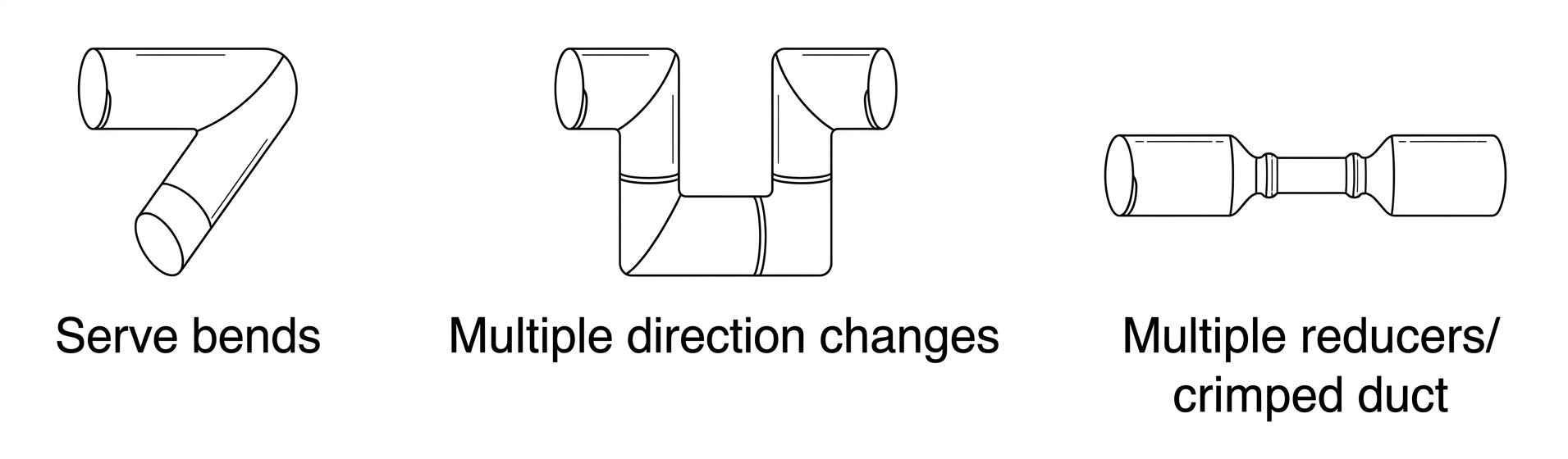
- Avoid excessive use of flexible duct and long flexible duct runs.
- Fire dampers must be installed in accordance with national and local fire regulations.
- Do not expose the unit to ambient temperatures above 104°F (40°C) or to open flames.
- To prevent exhaust air from re-entering the building, keep the two outdoor vents at least 39-3/8 inches (1,000 mm) apart.
- The heater must be operated in sync with the unit, ensuring it only starts when the unit does.
- To reduce indoor noise, consider installing a duct muffler.
- Improper installation may result in injury, equipment damage, or excessive vibration. An uneven installation will affect the unit’s performance.
- Protect the unit and its accessories from dust and debris during installation and on-site storage. Install service ports to allow access for filter maintenance.
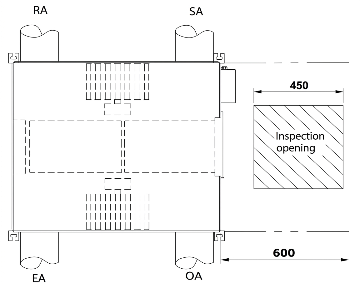
- Ensure the ceiling height is no less than the figures in the table column.
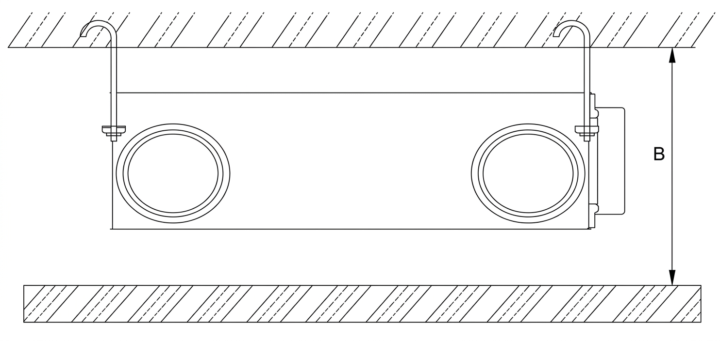
Model Inner Ceiling Height ERV100AHCLCO2L 340 ERV160AHCLCO2L 340 ERV200AHCLCO2L 390 ERV320AHCLCO2L 390
- Avoid the following scenarios during the ducting installation.
Installation Procedure
A. Preparing the Anchor Bolts
Fit the washers and nuts onto the pre-installed M10 or M12 anchor bolts. For M10 anchor bolts, the outer diameter must be at least 7/8 inch (21 mm); for M12 anchor bolts, it must be at least 1 inch (24 mm).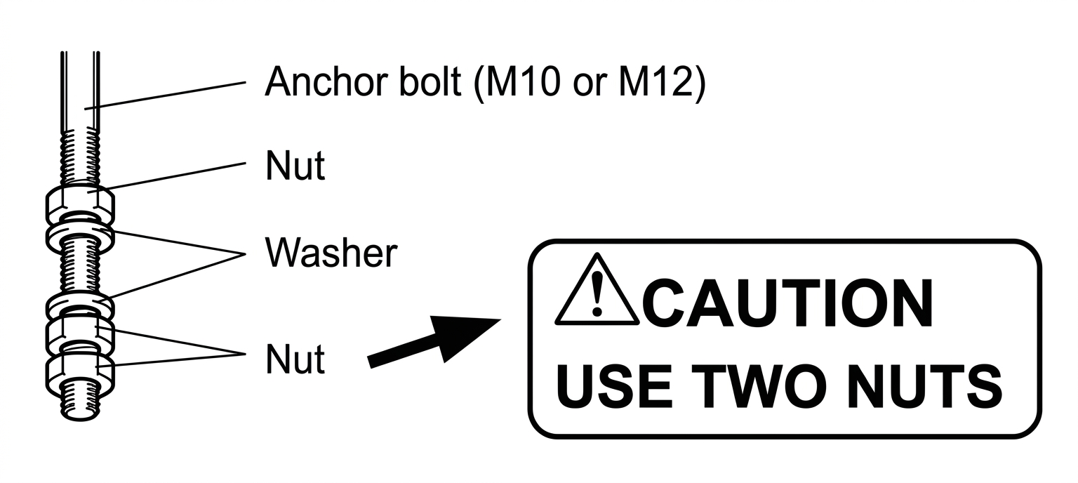
Using customer-supplied vibration isolation rubber may reduce mounting strength. We recommend the following installation method. 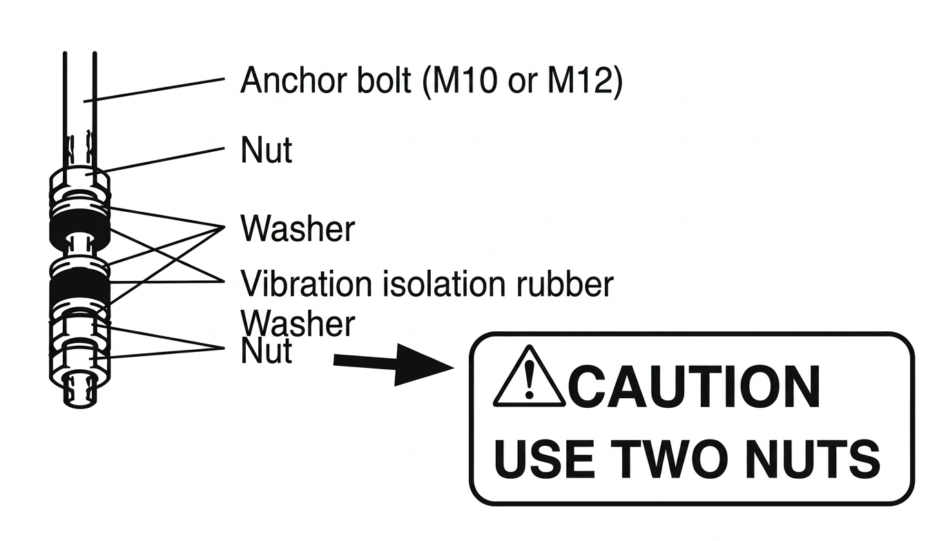
B. Hanging the Equipment
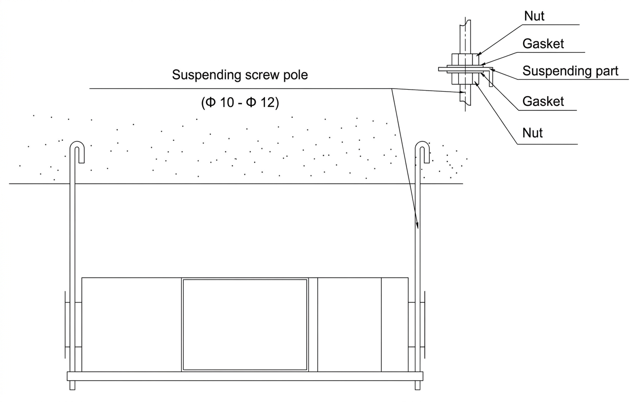
- Prepare suitable threaded hangers with adjustable nuts and gaskets.
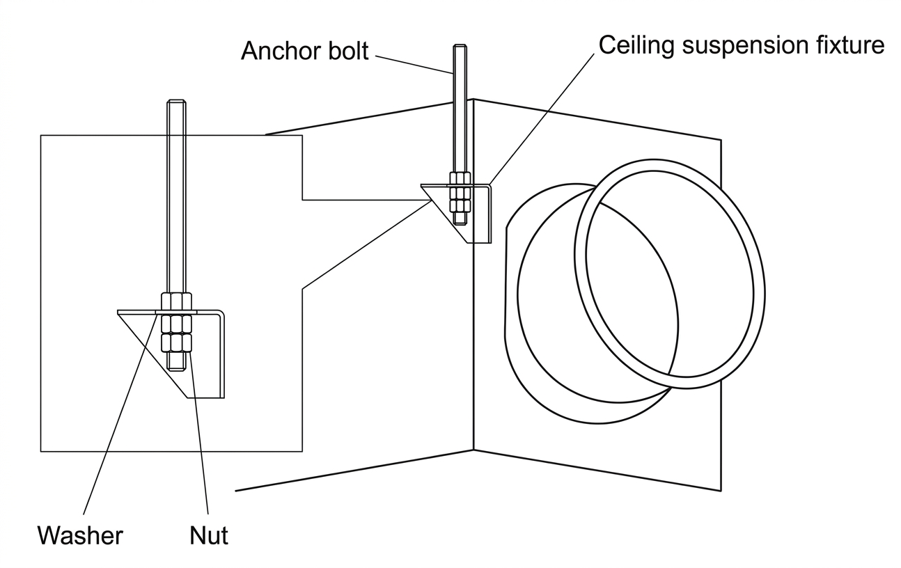
- Hang the ceiling suspension fixture on the anchor bolts and adjust the nuts until the unit is level. If the labels on the unit appear upside down, the unit has been installed upside down.
- Secure the ceiling suspension fixtures with double nuts.
- The unit must be level and securely fastened. Install the unit as shown in the image below.
Duct Connections
Standard Installation Examples
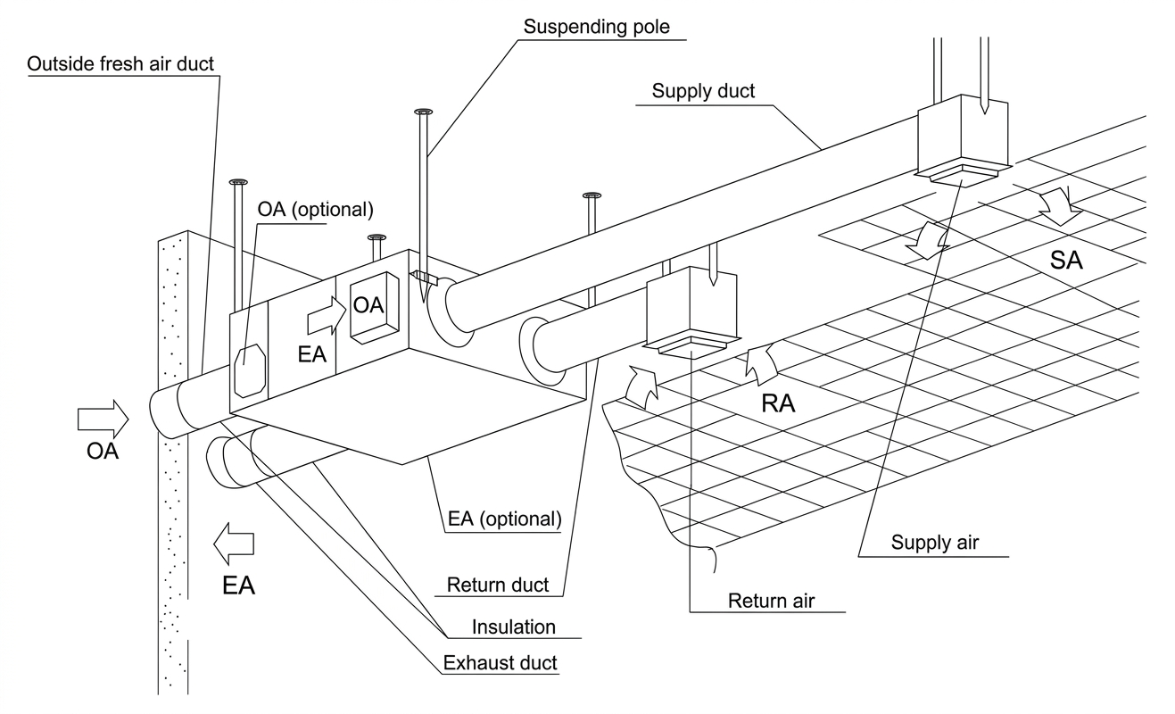
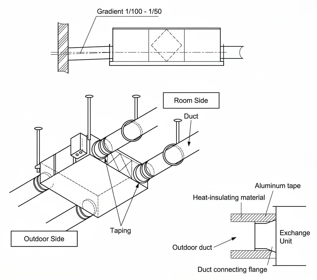
- Fasten the duct securely to the connecting flange and apply aluminum tape (field-supplied) around the joints to prevent air leakage.
- Support the ducts from the ceiling so their weight does not rest on the unit.
- Insulate the two outdoor ducts to prevent condensation. Material: glass wool; thickness: 1 inch (25 mm).
- Slope the two outdoor ducts downward toward the outside (slope of 1/100–1/50) to prevent rainwater from entering.
Electrical Installation
The power supply is 120 V AC, 60 Hz, single-phase. We recommend using a cable clamp to secure the power cable to the wall or the unit.
Warning
- To avoid electric shock, make sure the power supply is turned off during installation and before maintenance.
- Use cables that meet the specified requirements. Cables that do not meet these requirements may cause malfunction, electric shock, or fire.
- We accept no liability for any problems caused by unauthorized modifications to the electrical or control systems.
Steps
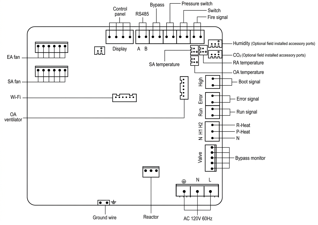
- Remove the electrical box cover and connect the three wires (L, N, and GND) to their corresponding terminals as shown in the wiring diagram.
- Connect the control panel cable to the circuit board, then secure the cable to the control panel.
Model Spec. of Power
Supply CableSpec. of Normal
Controller CableERV100AHCLCO2L to ERV320AHCLCO2L 3 x AWG #14 conductor 4 x AWG #22 conductor Power Supply Panel Type 120V~60Hz HDK-CK23C2 /
HDK-CK23C1 (optional)
Wiring Diagrams