Connect the Communication Cable for Wall-Mounted SystemsUpdated a month ago
Introduction
This article explains how to connect the communication cable for wall-mounted systems.
This article applies to the following systems:
- Diamante Essenza High-Wall (WYT-17)
- Diamante Pro High-Wall (WYT-20)
- Quantum Ultra High-Wall (WYT-24)
- Quantum Hyperformance High-Wall (WYT-25)
- Quantum Fresh High-Wall (WYT-FA)
Warnings
Before performing any electrical work, read these warnings:
General Warnings
- All wiring must comply with local and national electrical codes and regulations. A licensed electrician must install all the wiring.
- All electrical connections must be made according to the electrical connection diagram located on the panels of the indoor and outdoor units.
- If there is a serious safety issue with the power supply, stop work immediately. Explain the reasoning to the client and refuse to continue the installation until the safety issue is properly resolved.
Power Warnings
- The power voltage must be within 90-110% of the rated voltage. Insufficient power supply can cause a malfunction, electrical shock, or fire.
- Only connect the units to an individual branch circuit. Do not connect other equipment to the same power circuit.
Wiring Warnings
- Firmly connect every wire. Loose wiring can cause the terminal to overheat, resulting in product malfunction and possible fire.
- Keep the wiring away from the copper tube, as the refrigerant circuit can become extremely hot.
- Do not let wires touch or rest against the refrigerant tubing, compressor, or any moving parts.
- Do not cross the electrical wiring with the signal wiring. This may cause distortion, interference, or possibly damage to the circuit boards.
- Do not house wires of different voltages within the same wire tube. Avoid using metal wire tubes in environments prone to acid or alkali corrosion; use plastic wire tubes instead.
- Do not place wire connect joints inside the tubing. If a wire connect joint is necessary, use a connection box at the point of the joint.
Prerequisites
Complete these prerequisites before connecting the electrical wiring:
- Turn off the main power to the system. After powering off the system, wait 10 minutes or more before touching the electrical components in order to avoid electrical shock.
- Properly ground the system.
- If the unit has an auxiliary electric heater, install it at least 3-feet, 3-3/8-inches (1 m) away from any combustible materials.
- Install an external surge suppressor at the outdoor disconnect (recommended).
- When connecting power to fixed wiring, incorporate a properly rated, HACR-type circuit breaker or current leakage protection switch. It must disconnect all poles with a contact separation of at least 1/8 inch (3 mm). Use only an approved switch or circuit breaker with a capacity of 1.5 times the unit's maximum current.
Communication Cable Specifications
The 4-lead communication cable provides two power supply wires, one signal wire, and ground wire. The wires are individually insulated and bundled together inside the outer protective jacket. These wires are also pre-fitted with U-lugs on their ends.
Communication Cable Specifications (All Models): AWG #16 x 4 Core TC-ER cable.
When connecting the communication cable consult the nameplate on the system for detailed electrical specifications.
The 115V systems take a single-pole breaker for the main circuit panel. 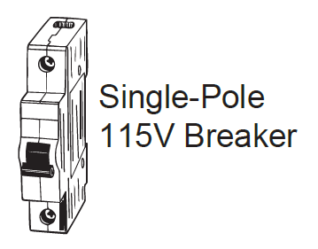
The 230V systems requires a double-pole breaker. The tandem-type will not work.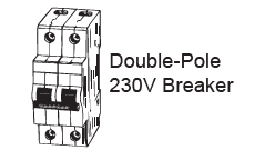
Connection Diagrams
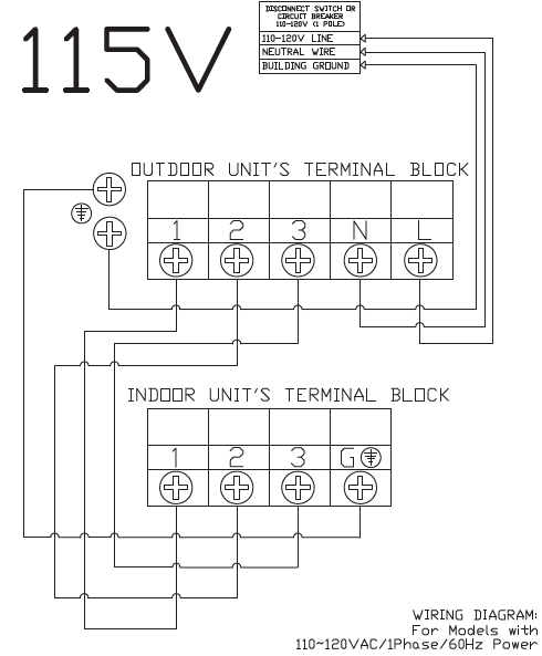
115V Systems
230V Systems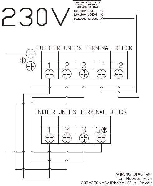
Connect the Cable
Connect the outdoor unit wires before connecting the indoor unit wires.
Outdoor Unit Wiring
1. Unscrew the electrical wiring cover and remove it. 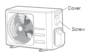
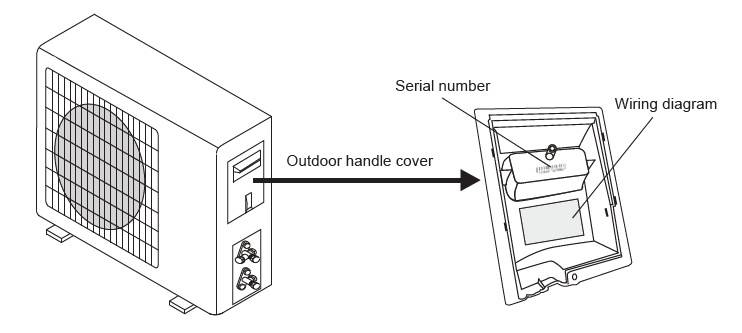
2. Connect the U-lugs to the terminals, matching the wire colors or labels with those on the terminal block. Firmly screw each U-lug to its corresponding terminal. Strictly follow the wiring diagram inside the electrical box cover when connecting the wires.
Select different colors for different wires according to relevant regulations. Ensure the wire colors for the wire colors for the outdoor unit and terminals match those used for the indoor unit.
Do not connect the power wire to the signal wire terminal. If the power and signal wires run parallel, place the wires in their own wire tube and maintain a gap of at least 11-3/4 inches (300 mm).
3. Secure the cable with the clamp. Ensure it is tight and does not pull on the U-lugs.
4. Reattach the cover.
Indoor Unit Wiring
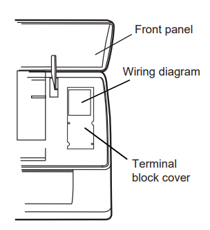
1. Lift up the indoor unit's front panel and remove the terminal block cover.
2. Connect the U-lugs to the terminals, matching the wire colors or labels with those on the terminal block. Firmly screw each U-lug to its corresponding terminal. Strictly follow the wiring diagram inside the electrical box cover when connecting the wires.
Select different colors for different wires according to relevant regulations. Ensure the wire colors for the wire colors for the outdoor unit and terminals match those used for the indoor unit.
Do not connect the power wire to the signal wire terminal. If the power and signal wires run parallel, place the wires in their own wire tube and maintain a gap of at least 11-3/4 inches (300 mm).
3. Secure the cable with the clamp. Ensure it is tight and does not pull on the U-lugs.
4. Reattach the cover and close the front panel.