Floor Mounting the Indoor Unit for UYT-24 Floor/Ceiling/Low-Wall Flex SystemsUpdated 3 months ago
Introduction
Learn how to floor-mount the indoor unit for the Quantum Ultra Floor/Ceiling/Low-Wall Flex (UYT-24) system.
This indoor unit can be mounted to either the floor or the ceiling, depending on your installation preferences. Read this other article for information on mounting the indoor unit to the ceiling.
Mounting Methods
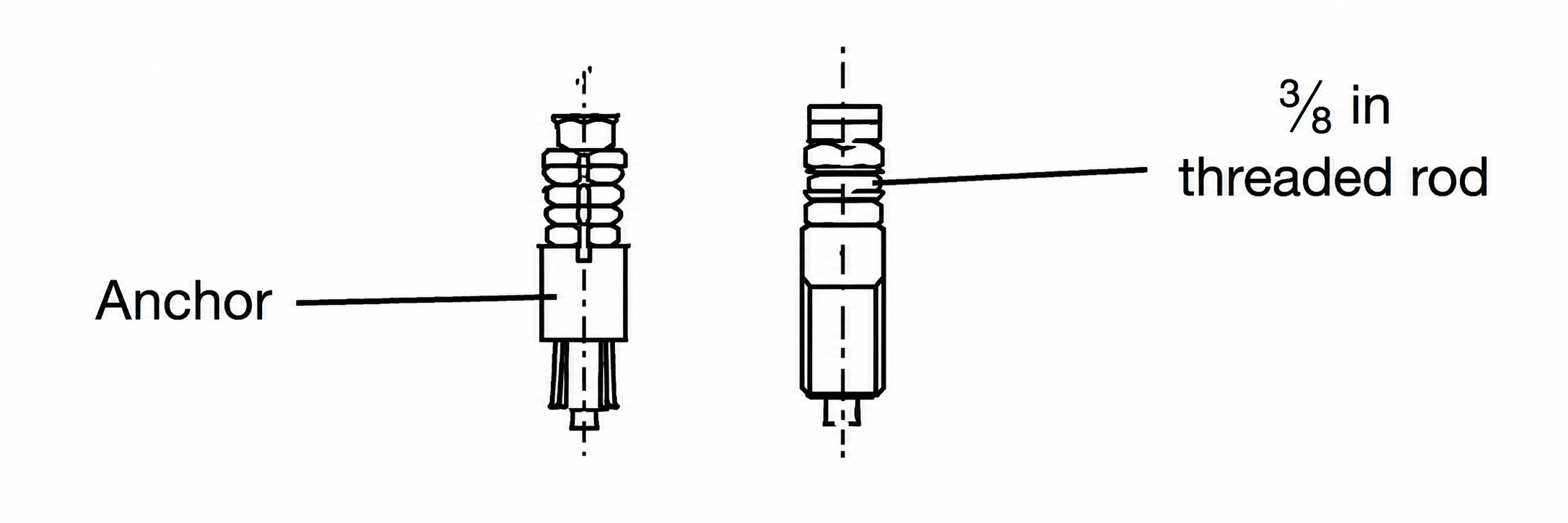
Finished Concrete (Brick or Slab)
Secure the hanging bolts directly into the concrete using expansion bolts. Drill to a depth of 1-3/4 - 2 inches (45-51 mm) to ensure secure anchoring.
New Concrete Bricks
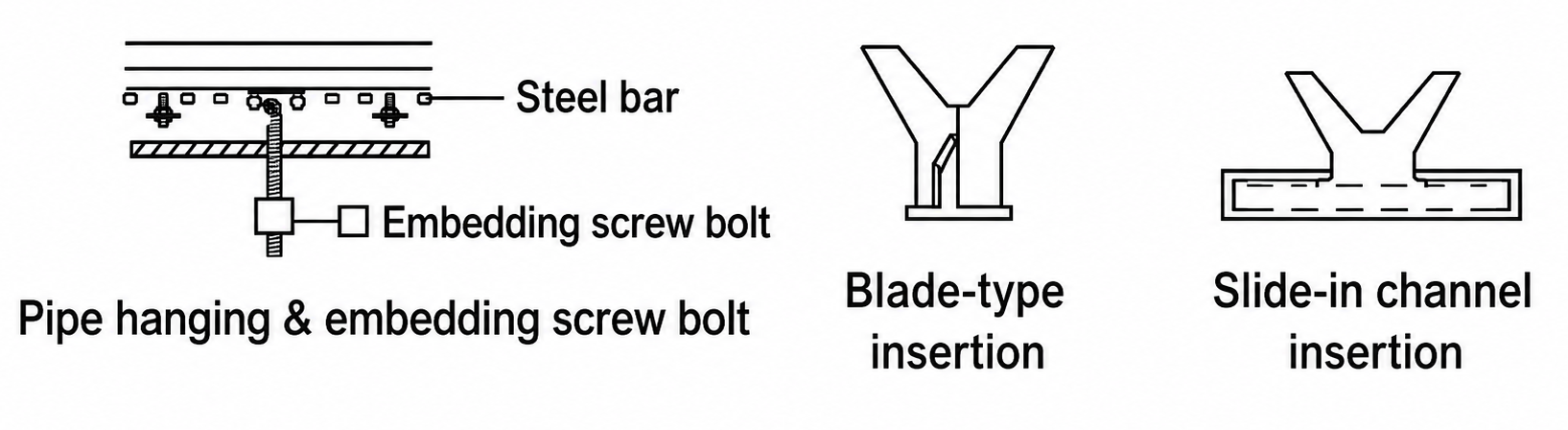
Use one of the following methods to embed the screw bolts:
- Blade-type insertion
- Slide-in channel insertion
Anchor the screw bolts firmly into the embedded steel reinforcement bars.
Steel Roof Beam Structure
Install the supporting steel angle brackets. Insert the hanging bolts through the brackets and secure them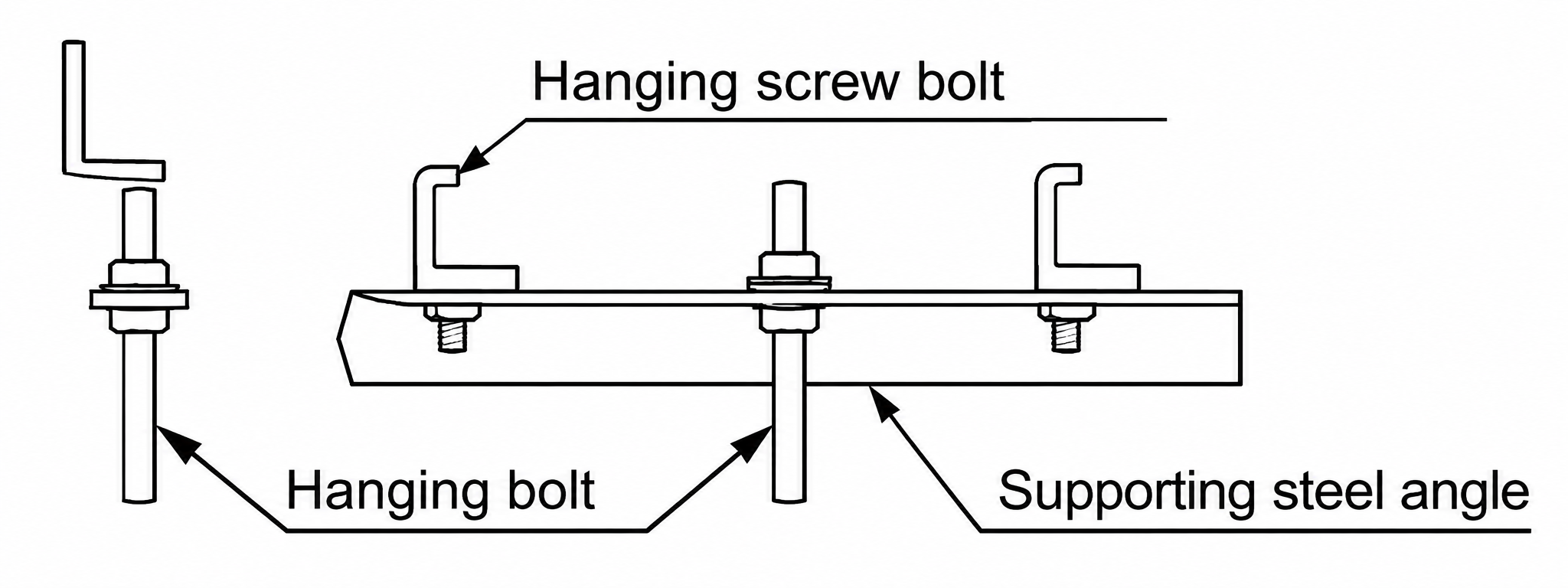
Wooden Construction
Secure the angle iron across the wooden joints, then attach the hanging bolts through the channel and into the ceiling structure. 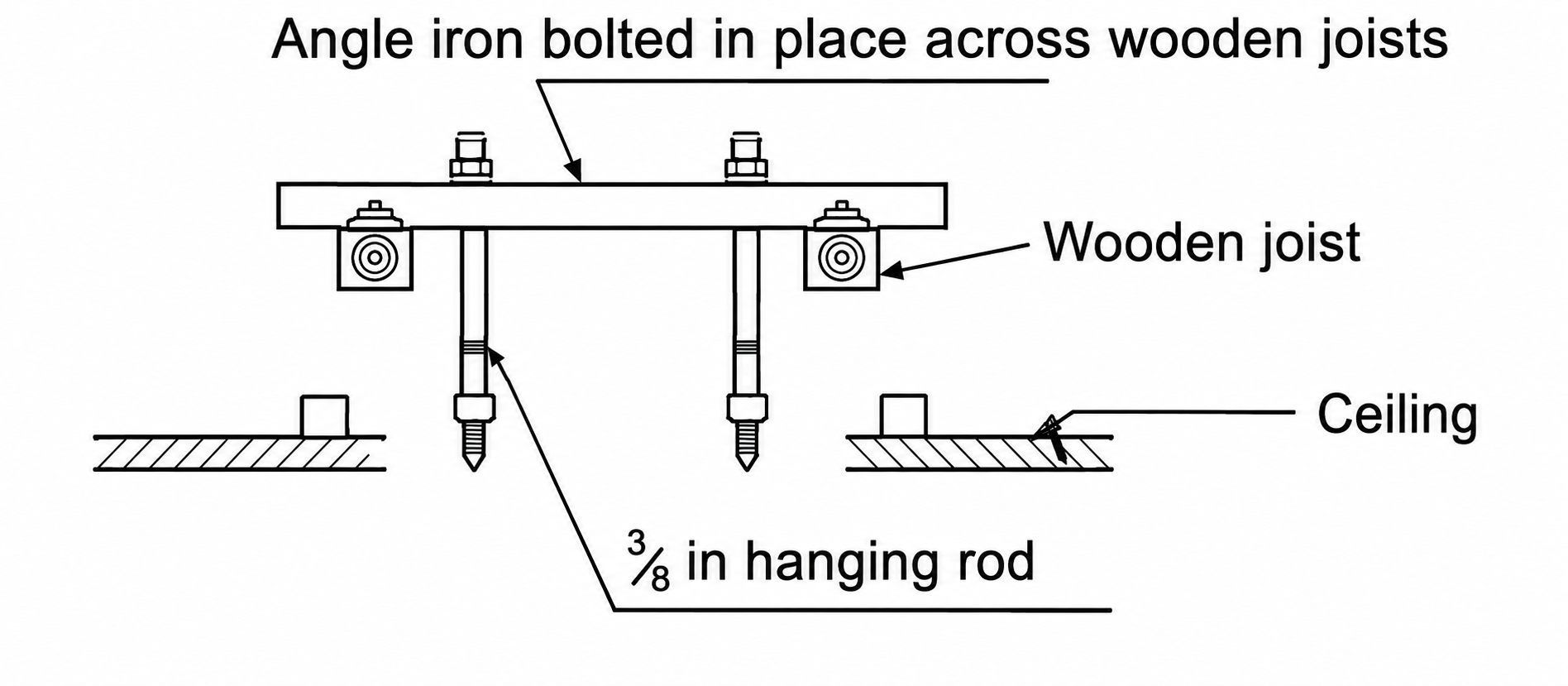
Pre-Installation Preparation
1. This indoor unit can be mounted to either the floor or the ceiling, depending on your installation preferences. Read this article for information on mounting the indoor unit to the ceiling.
2. Release and remove both side panels and the air handler's return grille, then set them aside.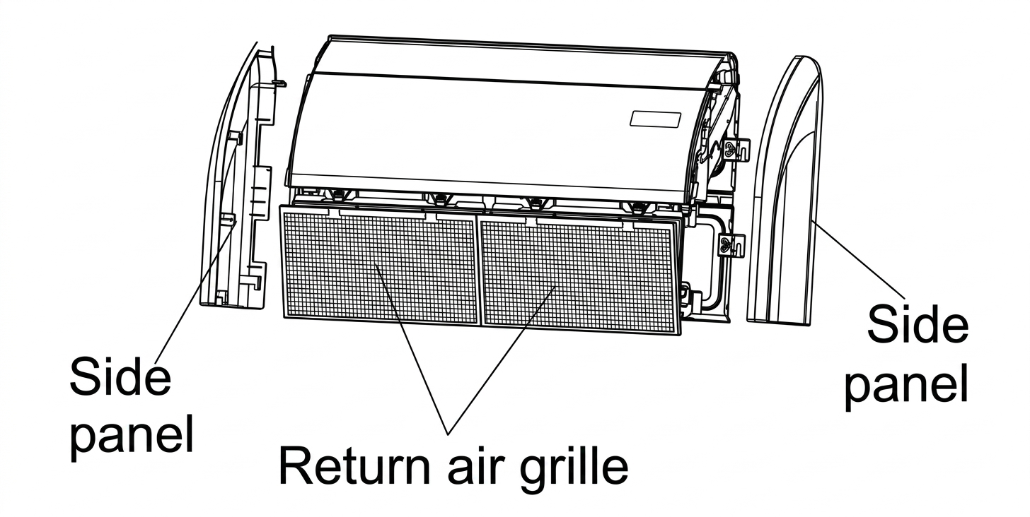
3. Select the exit pathway for the piping and drainage. Both rear and bottom options are available.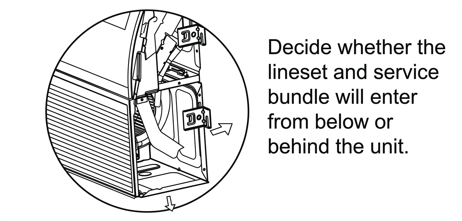
Hanging the Indoor Unit
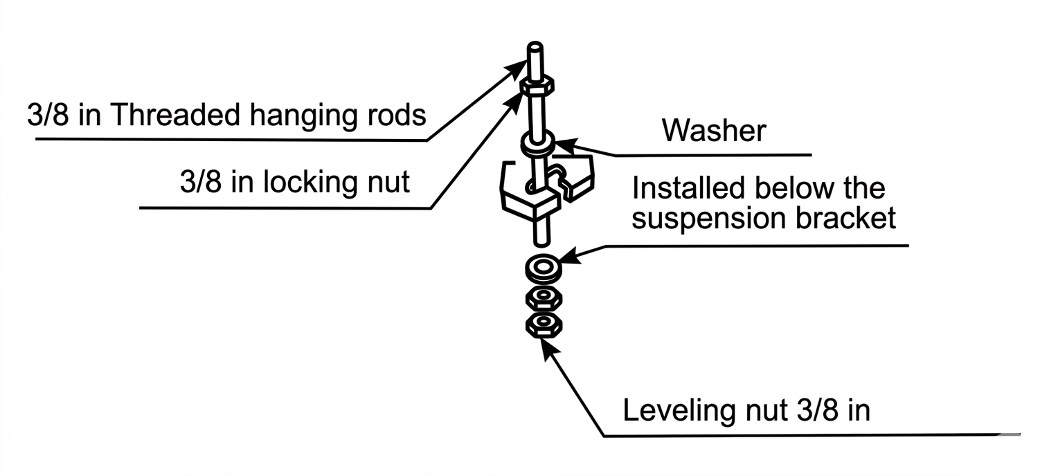
1. Hang the indoor unit using four field-provided 3/8-inch mounting bolts, eight washers, and eight nuts.
2. Ensure the center-to-center distance between bolts matches the specifications for the unit size.
3. Follow the installation diagram and measurements in this manual to install the hanging bolts.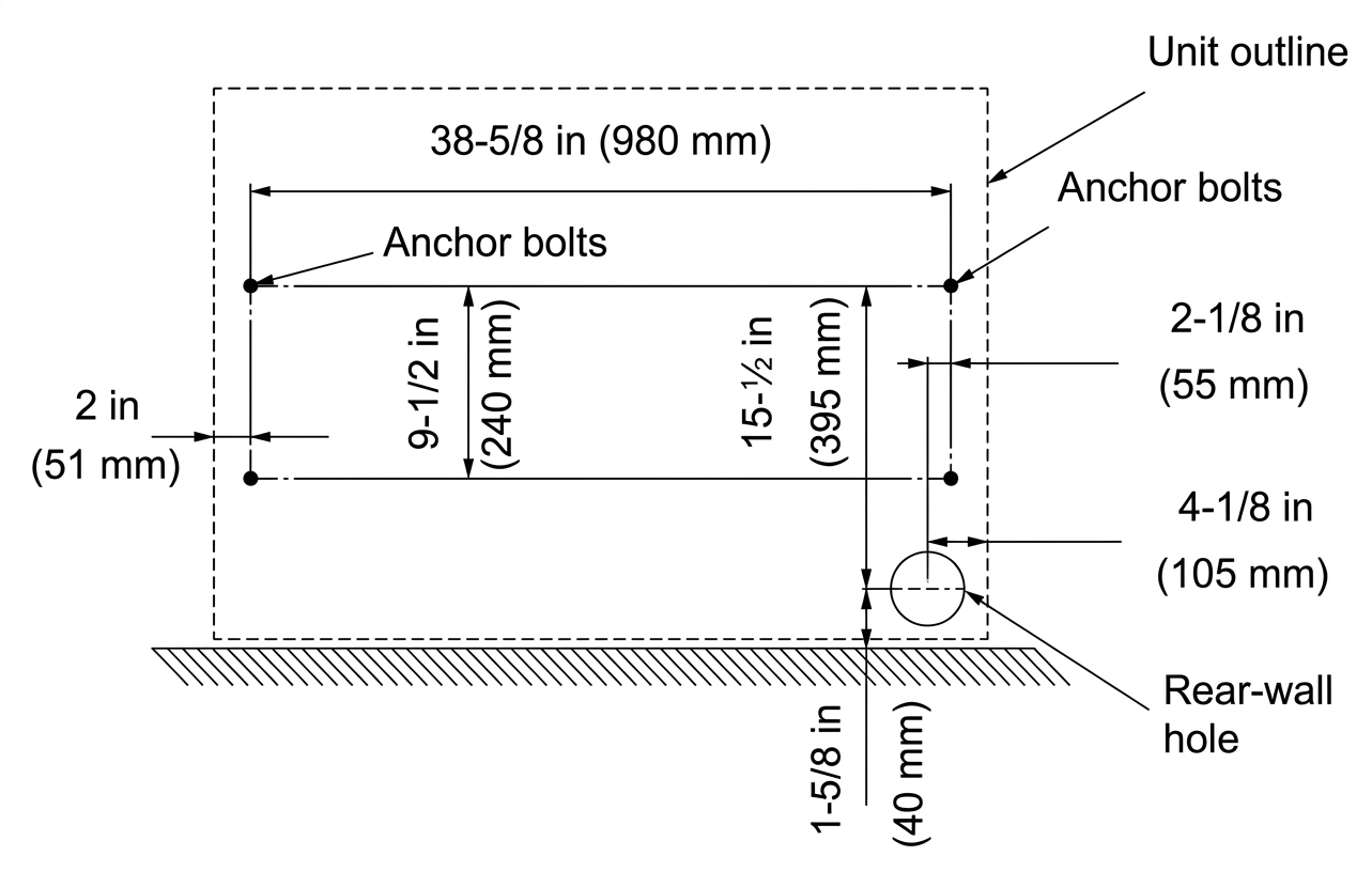
4. Confirm that the bolts are properly spaced and perfectly level.
5. Mount the indoor unit onto the installation bolts.
6. Confirm the unit is perfectly level before continuing.
Final Mounting Notes:
- Secure the final assembly using a 3/8-inch locking nut. Fine-tune the adjustment until the handler is level.
- Tighten all nuts firmly to ensure a stable, vibration-free installation. Re-check the levelness.
- Maintain an upward slope of 1-2/100 for proper drainage.
- The air gap should be 3/4 inch (19 mm) or less.
Assembly Notes
Attach components in the following order:
- Nut (upper)
- Gasket (upper)
- Suspension bracket
- Gasket (lower)
- Nut (lower)