IDU Disassembly for Quantum Hyperformance High-Wall SystemsUpdated 18 days ago
Introduction
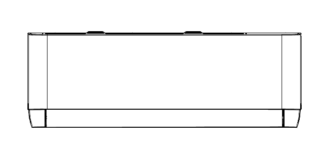
This article provides steps for disassembling the indoor unit of Quantum Hyperformance High-Wall (WYT-25) systems.
Indoor Unit Disassembly
Before disassembly:
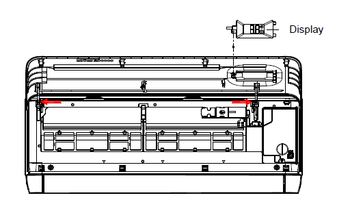
1. Disassemble the front panel and display board.
A. Open the front panel.
B. Remove one screw, then take out the display box from the panel.
C. Release the panel axis, which is shown in red arrows, out from the middle frame.
D. Remove the panel.
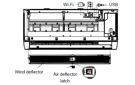
2. Remove the louver and take out the Wi-Fi module from the middle frame.
A. Remove the air guide by sliding the air guide pin to the right. The pin stays on the air guide after removing the air guide.
B. Slide the Wi-Fi module to the left to remove it.
C. Remove the Wi-Fi retaining cover from the retaining clips.
D. Remove the USB cable.
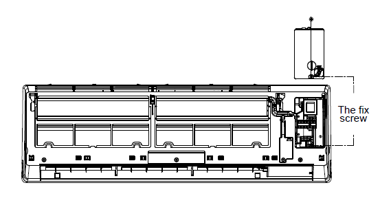
3. Remove the electronic control box cover.
A. Unfix one screw on the cover of the electric box.
B. Remove the cover.
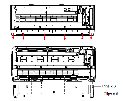
4. Remove the front cover plate.
A. Press the red arrow to loosen the six fixed clips between the front cover and center frame.
B. Rotate the front cover plate outward to disengage the fixing pins of the front cover plate and center frame.
C. Remove the front cover plate.
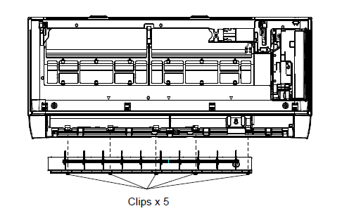
5. Remove the sweep blade assembly
A. Remove the sweep blade assembly by loosening the five clips from the base upwards.
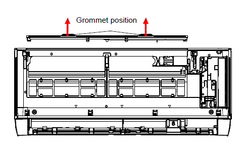
6. Remove the filter.
A. Pinch the top of the strainer at the grommet position, then slightly press upward to remove the strainer.
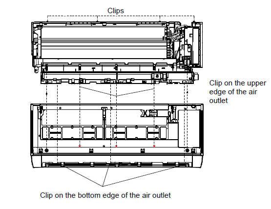
7. Disassemble the middle frame.
A. Remove the two fixing screws between the center frame and base.
B. Loosen the four fixing clips between the upper part of the center frame and base.
C. Press downward to loosen the three fixed clips between the center frame and upper edge of the air vent on the base, according to the position indicated by the arrow of the center frame.
D. Following the arrow in the center frame to indicate the position, press outward to loosen the three fixed clips between the center frame and lower edge.
E. Remove the center frame upwards.
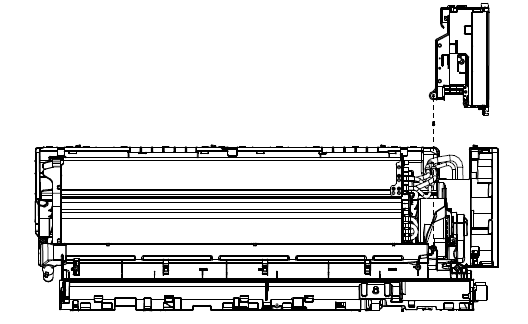
8. Disassemble the electronic control box.
A. Remove the electric control box and base fixing screws.
B. Remove the control box.
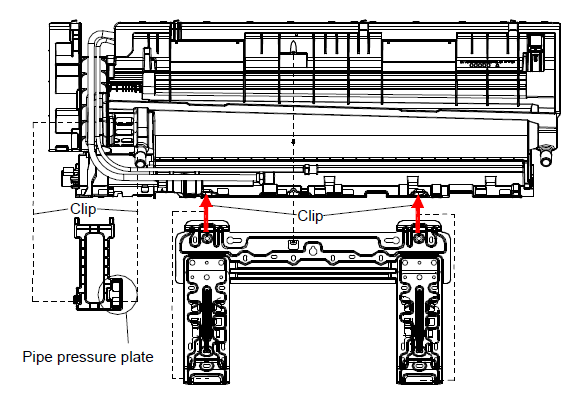
9. Remove the wall panels and pipe pressure plates.
A. Loosen the fixing screws of the wall plate and base.
B. According to the direction of the arrow, press the fixing clips on the base wall plate. Loosen the wall plate and base fixing clips, then remove the wall plate.
C. Hold the pipe pressure plate gripper position upward, then loosen the pipe pressure plate and the base of the fixed clips.
D. Remove the pipe pressure plate.
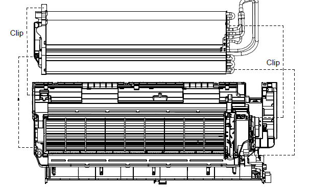
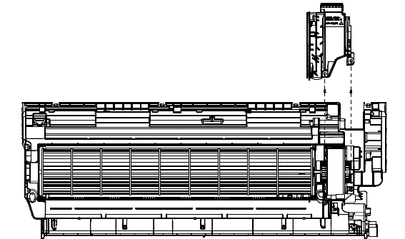
10. Disassemble the evaporator.
A. Remove the evaporator and base fixing screws.
B. Loosen the left side of the evaporator and the base fixing buckle.
C. Lift the left side of the evaporator upward.
D. After the left side of the evaporator is lifted, the right side of the evaporator will loosen. The evaporator can be taken out.
11. Remove the motor cover.
A. Remove the motor cover and the two fixing screws on the base to take out the motor cover upwards.
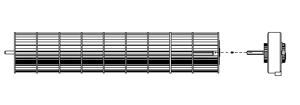
12. Remove the cross-flow fan and motor.
A. Remove the cross-flow fan and cross-flow fan motor upwards.
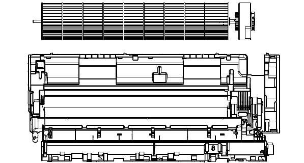
13. Remove the cross-flow fan motor.
A. Remove the motor from the cross-flow fan by taking out the mounting screws.