IDU Disassembly for Diamante Essenza / Diamante Pro / Quantum Ultra - High Wall MountUpdated 37 minutes ago
Introduction
This article provides steps for disassembling the indoor unit of Diamante Essenza (WYT-17), Diamante Pro (WYT-20), and Quantum Ultra - High Wall Mount (WYT-24) series systems.
Indoor Unit Disassembly
Before disassembly:
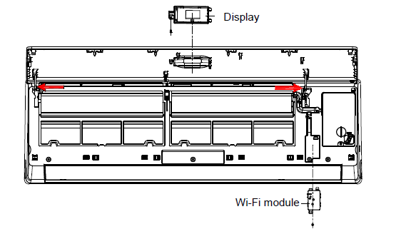
1. Disassemble the front panel, display board, and Wi-Fi module.
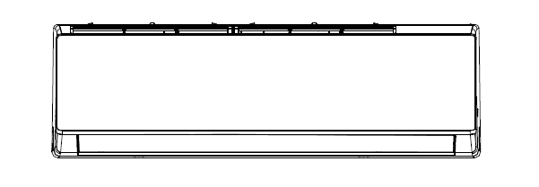
A. Open the front panel.
B. Remove one screw, then take the display box out from the panel.
C. Release the panel axis, which is shown in red arrows, out from the middle frame and take the panel out.
D. Unscrew and remove the Wi-Fi module from the middle frame.
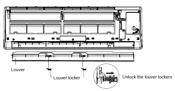
2. Remove the louver.
A. Unlock the louver lockers (clips).
B. Bend the louver slightly by hand and remove it from the middle frame and stepping motor.
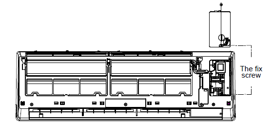
3. Remove the electronic control box cover.
A. Unfix one screw on the electric box cover.
B. Remove the electric box cover.
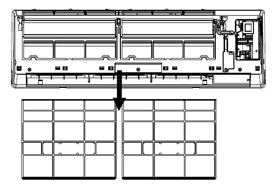
4. Remove the filter.
A. Push the filter upwards slightly and remove the filter from the unit.
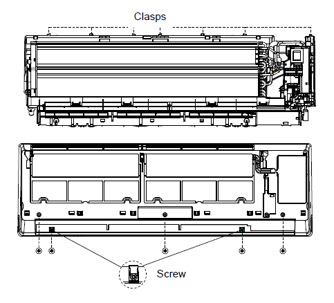
5. Disassemble the middle frame.
A. Open the screw cover and unfix the screw with a cross screwdriver.
B. Remove the middle frame by loosening the claps of the unit base.
C. Take the frame out.
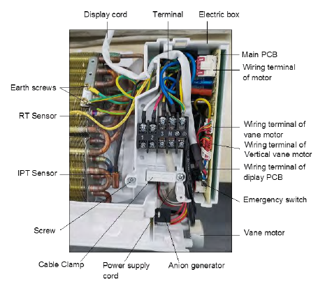
6. Disassemble the electronic control box.
A. Remove the RT (Room Temperature) and IPT (Indoor Pipe Temperature) sensors from the evaporator.
B. Unscrew all the earth ground wirings on the evaporator.
C. Take out all the connectors from the PCB (Printed Control Board).
D. Unfix one screw from the control box of the unit's base frame.
E. Remove the control box from the unit.
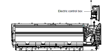
Note: The picture below is for reference only. The wiring connection for the exact model may by slightly different.
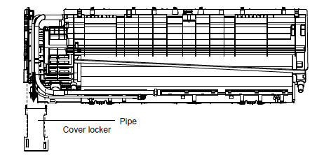
7. Remove the pipe cover.
A. Loosen the lower edge of the pipe cover from the base frame.
B. Remove the pipe cover from the unit.
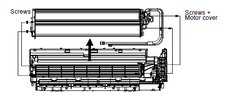
8. Disassemble the evaporator.
A. Unfix two screws on the left side.
B. Unfix two screws on the right side of the motor cover/right support plate.
C. Take out the evaporator from the unit by uplifting the input/output pipes slightly.
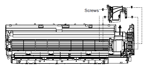
9. Remove the motor cover.
A. Unfix four screws on the motor cover of the base frame.
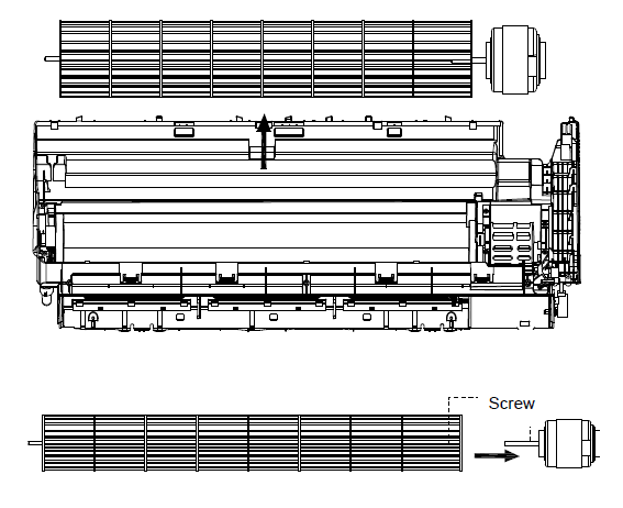
10. Disassemble the fan motor and fan blade.
A. Lift the fan blade and fan motor, then take out the base frame.
B. Unfix one screw on the axis of the fan motor.
C. Separate the fan motor and fan blade.