P1 or PC01 Error CodesUpdated 4 months ago
Introduction
The "P1” or “PC01” error codes indicate a voltage error is present. This article is for discontinued Quantum series systems (WYS, CYB, RYB, UYB, and FYB).
Prerequisites
Recommended parts to prepare:
- Power supply wires
- IPM module board
- Printed circuit board (PCB)
- Reactor
Video Tutorial
Watch this video tutorial to learn how to troubleshoot the "P1" or "PC01" error codes:
P1 Error Codes Service and Diagnostic
Video length: 2:10
Troubleshooting
Note: An HVAC professional may be required for assistance.
The troubleshooting recommendations include:
- Ensure that the unit has the proper breaker. The Quantum series systems require a standard single (110V) or double (220V) pole breaker. The unit will not work with a tandem-double pole or GFCI/AFCI breaker. Note: You can send photos to our Technical Support team to confirm the proper breaker.
- Ensure that the indoor and outdoor model numbers match in series, BTU sizing, voltage, and compatible SEER levels.
- Check if the wiring terminations are correct. The 1, 2, 3 configuration has to match in color sequence outside and inside.
- Confirm the communication wiring is a solid run, containing no splices.
- Check for any physical damage along the wiring. You can run spare wire to confirm.
- If the wiring is correct, check the outdoor unit voltages. The outdoor unit voltages should read 220V or 110V.
- Check the AC voltage across terminals 1 + 2 on the indoor unit.
- Check the AC voltage across terminals 1 + 2 on the outdoor unit.
- Check the AC voltage across terminals L + N (or L1 + L2) on the indoor unit.
- If the outdoor unit voltages are correct, check the compressor. Note: Checking the compressor requires turning the unit’s power completely off.
- Remove the top and front panels of the unit.
- Ohm Ω out the compressor lead pairs on the Molex plug between the compressor and board. The three pairs of leads on the compressor side of the plug should match and all be between 1-3.
- Test each wire individually against the ground using the metal casing of the unit or a ground screw. The wires should not have any reading against the ground. The compressor should not be grounded. The multimeter should read “0” or “Open Line.”
- If the compressor operates properly, check the unit’s reactor. Note: Not all unit’s have reactors.
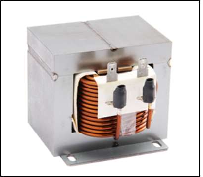
- Unplug the two leads.
- Test the two leads. The two leads should read between 0-to-1-ohm Ω.
- If the unit’s reactor operates properly, the outdoor mainboard needs replacing. If the unit’s reactor is not functioning properly, replace the reactor.
Note: Contact our Parts and Warranty department for any replacement components. Call 1-800-919-0150; Option #4.
If you need to see the correct wiring of the compressor, see the Related Resources section at the bottom of the article.
If you need information on how to open the outdoor condenser unit, see the Related Resources section.
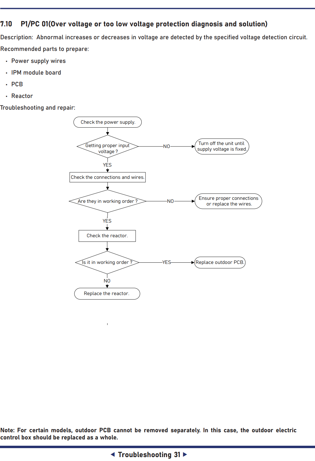
Troubleshooting Diagram
Scope of Models Covered
Single-Zone Mini Split Systems | Multi-Zone and Light Commercial Mini Split Systems |
| YN009AMFI20RPD / WS009AMFI20HLD | YN020GMFI22M2E |
| YN009GMFI20RPD / WS009GMFI20HLD | YN030GMFI22M3E |
| YN012AMFI20RPD / WS012AMFI20HLD | YN040GMFI22M4E |
| YN012GMFI20RPD / WS012GMFI20HLD | YN050GMFI22M5E |
| YN018GMFI20RPD / WS018GMFI20HLD | CB009GMFILCFHD / CB012GMFILCFHD / CB018GMFILCFHD / CB024GMFILCFHD |
| YN024GMFI20RPD / WS024GMFI20HLD | RB009GMFILDFHD / RB012GMFILDFHD / RB018GMFILDFHD / RB024GMFILDFHD |
| YN030GMFI20RPD / WS030GMFI20HLD | FB012GMFILDFHE / UB018GMFILCFHD / UB024GMFILCFHD |
| YN036GMFI20RPD / WS036GMFI20HLD | WS009GMFI22HLE / WS012GMFI22HLE / WS018GMFI22HLE / WS024GMFI22HLE |
| YN009AMFI22RPE / WS009AMFI22HLE YN012AMFI22RPE / WS012AMFI22HLE | YN009GMFI22RPE / YN012GMFI22RPE / YN018GMFI22RPE / YN024GMFI22RPE |
Related Resources
- For information on the correct wiring for the compressor, see page 21 in this manual: Quantum Inverter Series Service & Troubleshooting manual
- See page 90 in this manual to learn how to open the outdoor condenser unit: Quantum Inverter Series Service & Troubleshooting manual