E3, EH 03, F5, or EC 07 Error CodesUpdated 4 months ago
Introduction
The "E3", "EH 03", "F5", or "EC 07" error codes indicate the speed of the indoor or outdoor fan is operating outside of its normal range. The "E3" and "EH 03" error codes indicate the indoor fan is operating outside of its normal range, while the "F5" and "EC 07" errors codes indicate the outdoor fan. This article is for discontinued Quantum series systems (WYS, CYB, RYB, UYB, and FYB).
If the speed of the indoor or outdoor fan remains too low or high for a certain time, the LED display will show the failure code, resulting in the system to turn off.
Prerequisites
Recommended parts to prepare:
- Connection wires
- Fan assembly
- Fan motor
- Printed circuit board (PCB)
Troubleshooting
Note: An HVAC professional may be required for assistance.
The troubleshooting recommendations include:
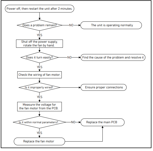
- Power off the unit and restart it after 2 minutes. If the problem continues, shut off the power supply and rotate the unit's fan by hand.
- Check if the unit's fan is turning easily. If the fan is turning easily, check the wiring of the fan motor.
- Ensure that the fan motor is properly connected and wired.
- Measure the voltage for the fan motor from the PCB. Note: Refer to the Measuring Fan Motor Voltage section for information on measuring fan motor voltage.
- If the voltage is within the normal parameters, replace the fan motor.
- If not, replace the main PCB. Note: For certain models, the outdoor PCB cannot be removed separately. In this case, the whole outdoor electric control box should be replaced.
Measuring Fan Motor Voltage
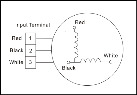
- Indoor or Outdoor DC Fan Motor (Control Chip in Fan Motor): Power on the unit and wait until it is in standby mode. Measure the voltage of pin1-pin3 and pin4-pin3 in the fan motor connector. If the value of the voltage is not within the range displaying in the tables below, the PCB has faulted and needs replacing.
- DC motor voltage input and output (voltage: 220-240V~):No.ColorSignalVoltage1RedVs/Vm280V2---------3BlackGND0V4WhiteVcc14-17.5V5YellowVsp0~5.6V6BlueFG14-17.5V
- DC motor voltage input and output (voltage: 115V~):No.ColorSignalVoltage1RedVs/Vm140V~190V2---------3BlackGND0V4WhiteVcc14-17.5V5YellowVsp0~5.6V6BlueFG14-17.5V

- DC motor voltage input and output (voltage: 220-240V~):
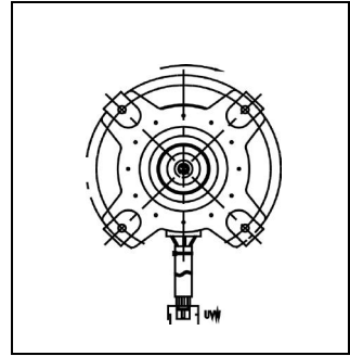
- Outdoor DC Fan Motor (Control Chip is in Outdoor PCB): Release the UVW connector. Measure the resistance of U-V, U-W, and V-W. If the resistance isn't equal to each other, the fan motor has faulted and needs replacing. Otherwise, the PCB has faulted and needs replacing.
- Indoor DC Fan Motor: Power on the unit and set it to run in Fan mode at high fan speed. After letting the unit run for 15 seconds, measure the voltage of pin1 and pin2. If the value of the voltage is less than 100V (208~240V power supply) or 50V (115V power supply), the PCB has faulted and needs replacing.