Installing ECOasis 150 Energy Recover VentilatorsUpdated 6 days ago
Introduction
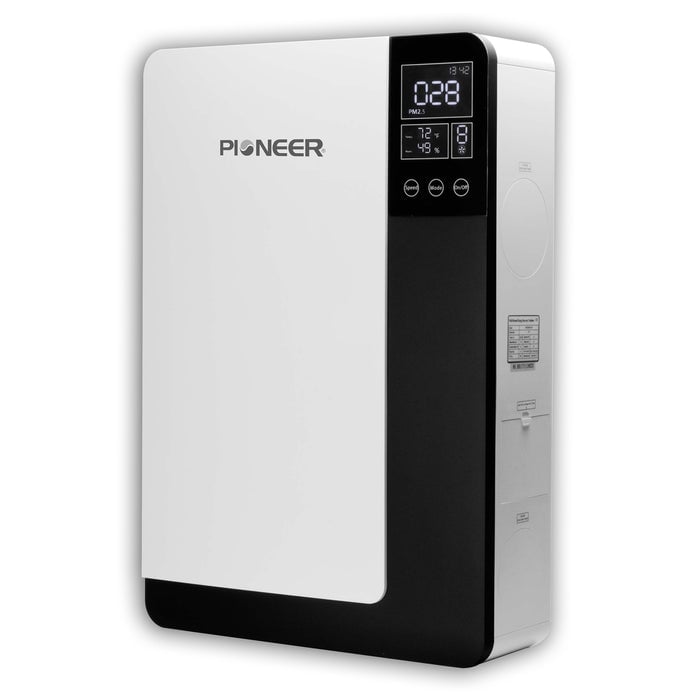
Follow this procedure to install the ECOasis 150 Ductless Wall-Mounted Single-Room Energy Recovery Ventilator.
Two installation scenarios are available. Select either the rear or side of the equipment for the air inlets and outlets.
Rear Installation
1. Choose a suitable location on the wall to mount the equipment. Mark the intended locations for the outdoor air inlet and exhaust air outlet. Then, mark the five mounting holes for the installation panel.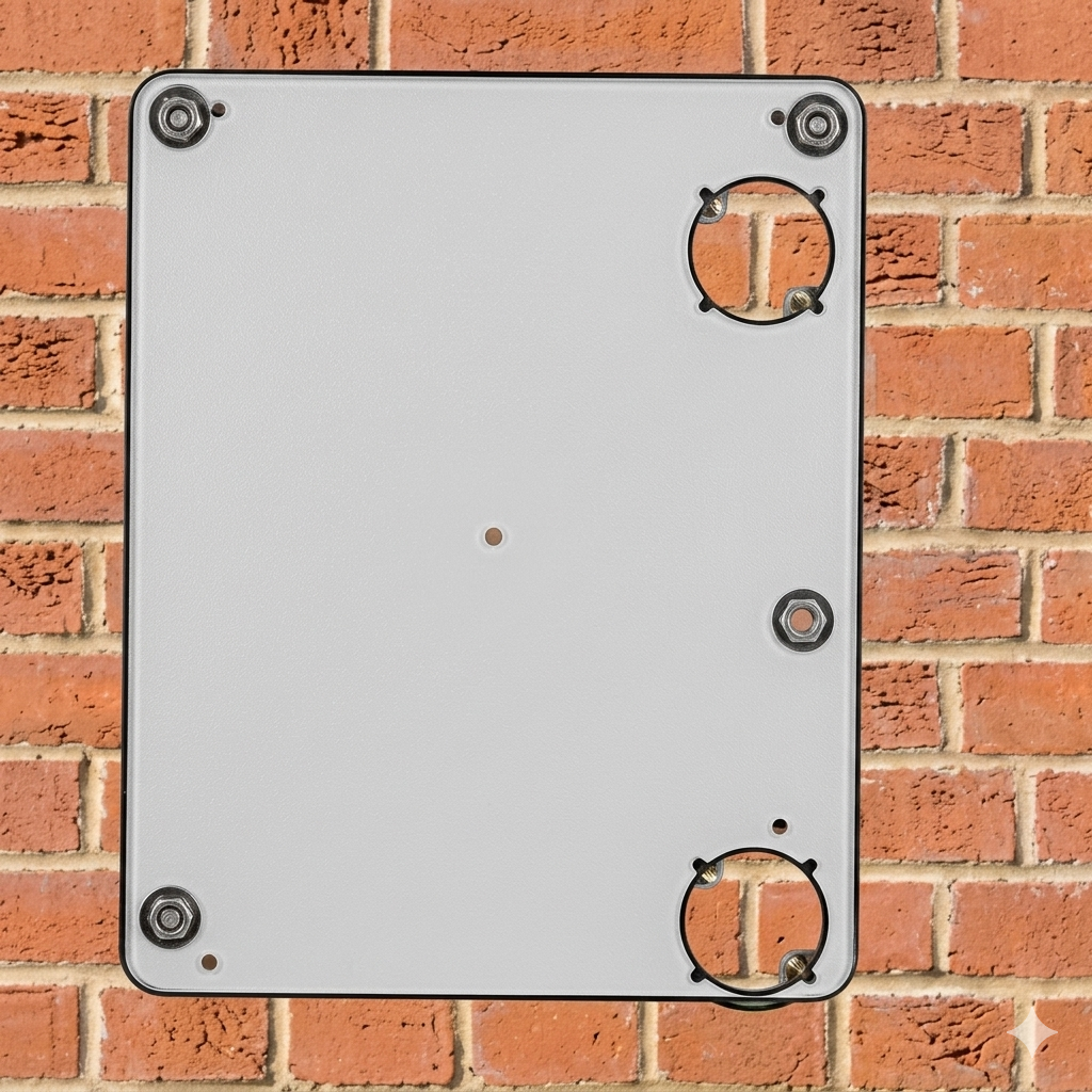
Clearances:
- Floor clearance: Maintain a distance of at least 5 feet (1.5 m) from the bottom of the ventilator to the floor.
- Wall clearance: Leave at least 1 foot (0.3 m) of space between the walls and both the left and right sides of the ventilator.
2. Drill two holes in the wall for the fresh air inlet and exhaust outlet, each measuring 4 inches (102 mm) in diameter.
- Angle the holes downward toward the outside at a minimum slope of 1/4 inch per foot (18 mm per meter) to prevent rainwater ingress.
- Use a 1/4-inch drill bit to make five mounting holes, each 2-3/4 inches deep (Ø 6 x 70 mm).
- Place the five plastic anchors into the mounting holes.
- The specified hole sizes for the outdoor air inlet and exhaust air outlet are based on the included Pioneer accessories (straight PVC pipes). If you use a different piping size, ensure the wall holes match accordingly.
3. Fasten the flange to the installation panel using the included M3 x 12 bolts and nuts. 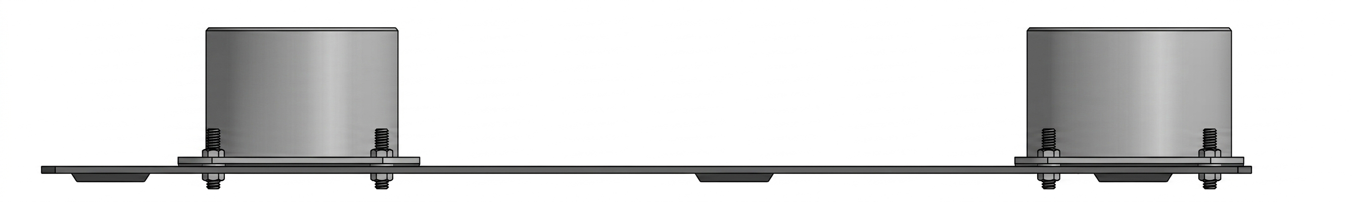
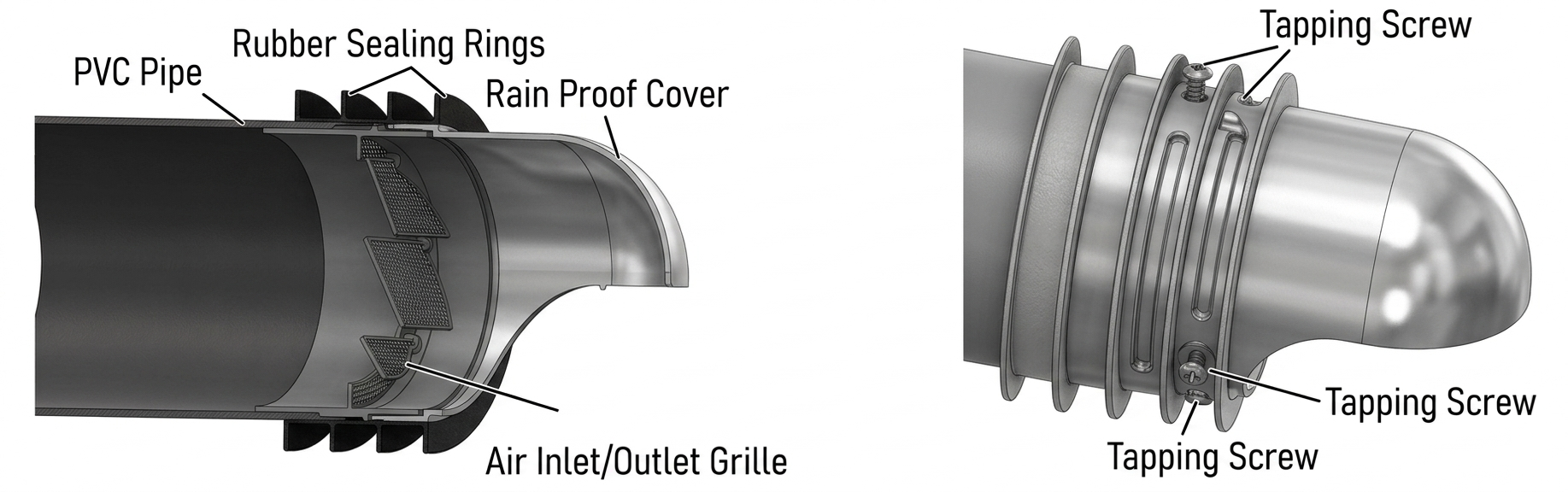
4. Measure the wall thickness and cut the PVC pipes to the appropriate length. Drill 1/8-inch (3 mm) holes before installing the fastening screws. Connect the pipes to the outdoor air and exhaust accessories as follows:
OA side: PVC pipe + Air inlet grille + Rain proof cover + Rubber sealing ring + Tapping screws
EA side: PVC pipe + Air outlet grille + Rain proof cover + Rubber sealing ring + Tapping screws
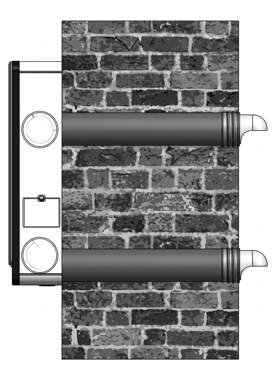
5. Slide the assembled ducts into the wall. Ensure the rain cover faces downward to prevent water ingress.
Next, seal any gaps between the duct and the wall using appropriate, field-supplied materials such as silicone or waterproof putty.
6. Secure the ERV installation panel onto the wall using the supplied knock-on anchor bolts.
7. Cut the EPS rear cover located at the outdoor air vent. Do not cut the EPS side cover during this installation.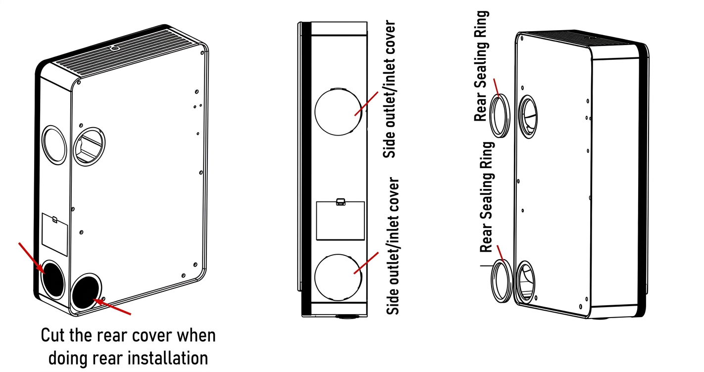
8. Install the two round outdoor and exhaust air covers over the side air inlet and side outlet.
Attach one seal ring to the rear of the air inlet and the other to the rear of the air outlet.
9. Secure the rear-plate thermal insulation foam (or cotton) to the back of the ventilator (near the outdoor air side), if needed. This prevents condensation from forming when operating the unit in cold areas.
10. Hang the ventilator on the installation panel. Adjust the four M5 x 18 hanging screws on the back of the ventilator to align with the installation panel slots.
11. After completing the installation, power on the ventilator.
Side Installation
1. Secure the two sealing rings onto the side flanges. Fasten the flanges to the side of the ventilator using the eight included M3 bolts and M3 nuts.
2. Cut the EPS side cover located at the outdoor air vent. Do not cut the EPS rear cover for this installation. 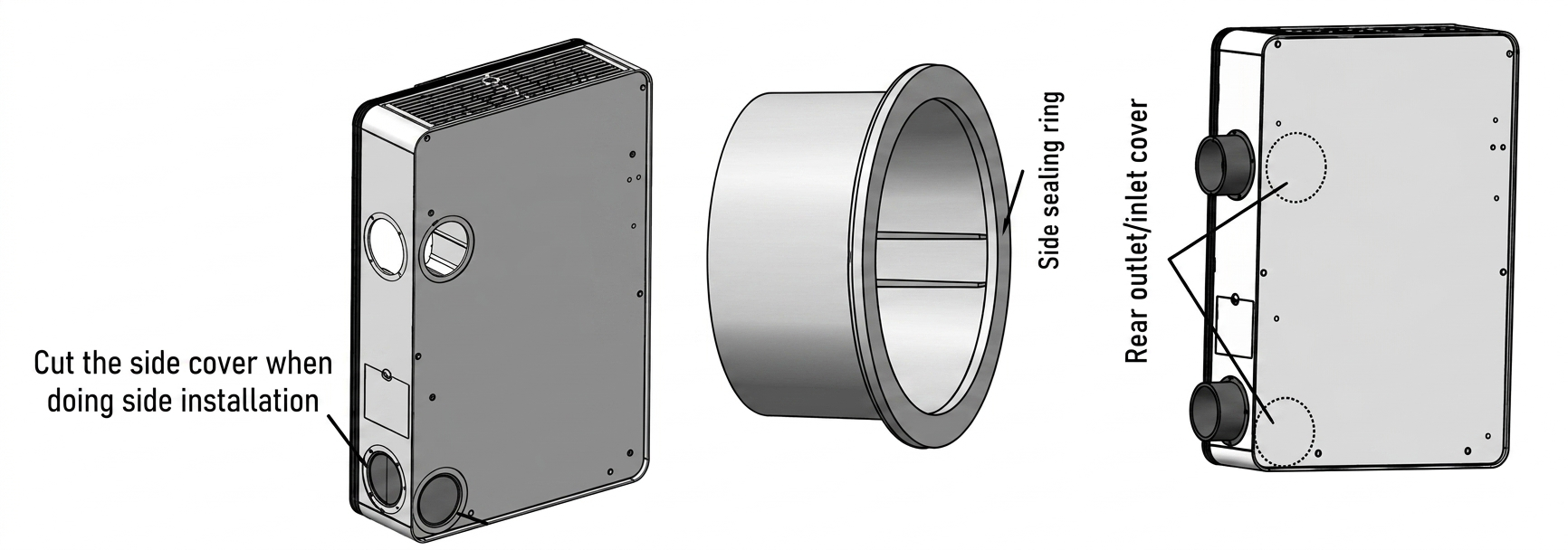
3. Choose a suitable location on the wall to mount the equipment. Mark the intended locations for the outdoor air inlet and exhaust air outlet. Then, mark the five mounting holes for the installation panel according to the ventilator placement.
Clearances:
- Floor clearance: Maintain a distance of at least 5 feet (1.5 m) from the bottom of the ventilator to the floor.
- Wall clearance: Leave at least 1 foot (0.3 m) of space between the walls and both the left and right sides of the ventilator.
4. Using the panel as a reference, drill five mounting holes with a 1/4-inch (6 mm) drill bit to a depth of 2-3/4 inches (70 mm). Push the five plastic anchors into the newly drilled mounting holes.
5. Drill two holes in the wall, each 4 inches in diameter, for the fresh air inlet and exhaust air outlet.
Angle the two holes downward toward the outside to prevent rainwater from entering. Maintain a minimum downward slope of 1/4 inch per foot (18 mm per meter).
The specified wall hole size is a recommendation only. For side installations, installers must supply and use flexible ducts. Select the final hole size based on the exact diameter of the duct being installed.
6. Mount the ventilator onto the installation panel. Adjust the four M5 x 18 hanging screws on the back of the ventilator to align with the panel.
7. Cut the PVC pipes to the appropriate length based on the wall thickness, then connect them to the outdoor air and exhaust accessories.
- OA side: PVC pipe + Air inlet grille + Rain proof cover + Rubber sealing ring + Tapping screws
- EA side: PVC pipe + Air outlet grille + Rain proof cover + Rubber sealing ring + Tapping screws
8. Slide the assembled ducts into the wall. Ensure the rain cover faces downward to prevent water entry.
Next, seal any gaps between the duct and the wall using appropriate, field-supplied materials such as silicone or waterproof putty.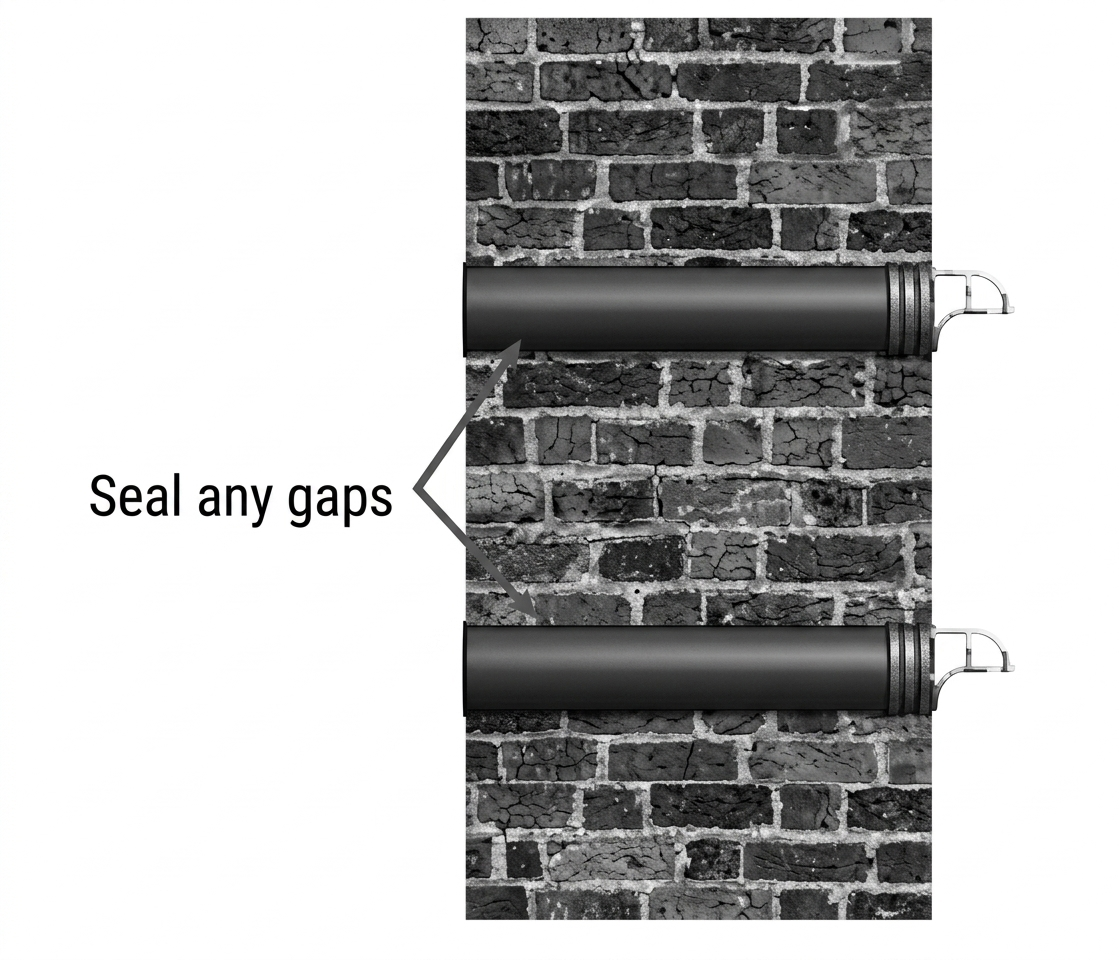
9. Attach the remaining end of the installed pipe to the flanges on the side of the ventilator.
10. After completing the installation, power on the ventilator.