
EC07, EH03, EH31, and EH32 Error CodesUpdated 18 days ago
These codes indicate an abnormal fan speed in either the outdoor or indoor unit.
- EC07 Error Code: An abnormal outdoor unit fan speed.
- EH03 Error Code: An abnormal indoor unit fan speed.
- EH31 and EH32 Error Codes: An indoor unit fan speed error.
If the indoor or outdoor fan speed stays too low or too high for a set period, the system stops operating and an error code appears on the LED display.
Recommended Parts to Prepare
- Connection wires
- Fan assembly
- Fan motor
- PCB
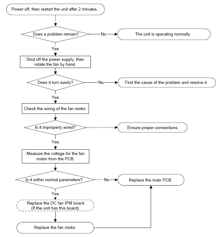
Index
Quantum Ultra 4-Way Ceiling Cassette (CYB-20), Quantum Ultra Single-Way Ceiling Cassette (CYK-24), and Quantum Ultra Floor-Mount (FYB-24)
Indoor or Outdoor DC Fan Motor (Control Chip in Fan Motor)
- Turn on the power and confirm that the unit is in standby.
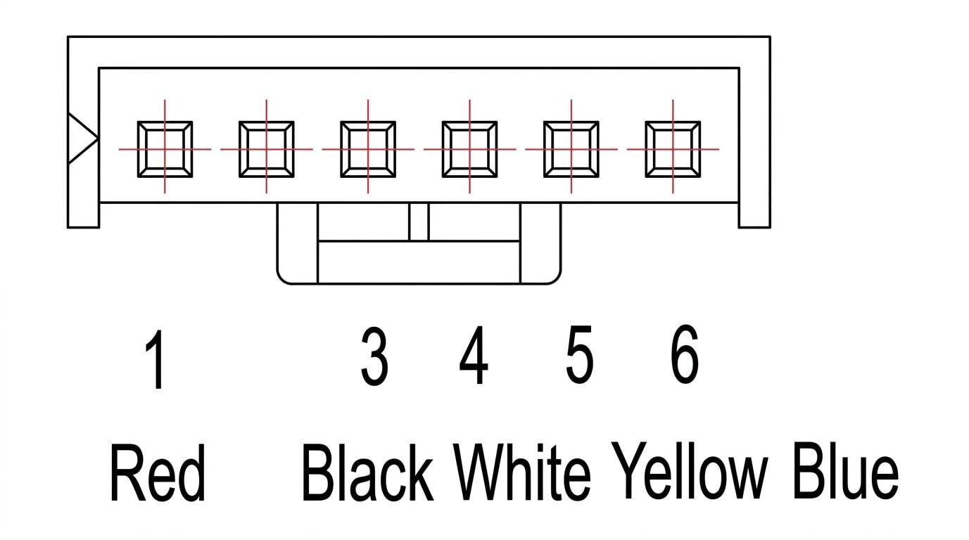
- On the fan motor connector, measure the voltage from pin 1 to pin 3 and from pin 4 to pin 3. If either reading is outside the range shown in the table below, replace the PCB.
| No. | Color | Signal | Voltage |
| 1 | Red | Vs / Vm | 192~380 V |
| 2 | - - - | - - - | - - - |
| 3 | Black | GND | 0 V |
| 4 | White | Vcc | 13.5~16.5 V |
| 5 | Yellow | Vsp | 0~6.5 V |
| 6 | Blue | FG | 13.5~16.5 V |
Outdoor DC Fan Motor (Control Chip in Outdoor PCB)
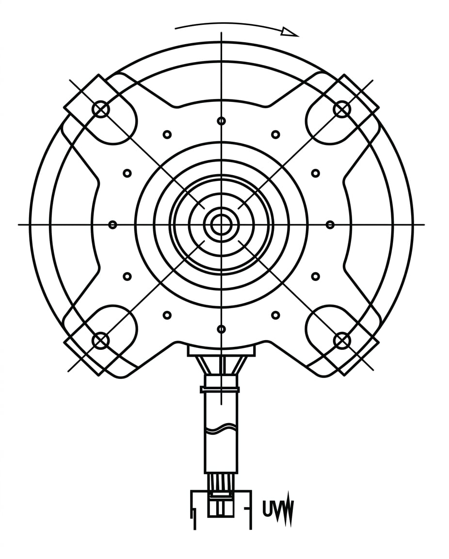
- Disconnect the UVW connector.
- Measure the resistance between U and V, U and W, and V and W. If the three readings are not equal, the fan motor is faulty and must be replaced. If they are equal, the PCB is faulty and must be replaced.
Quantum Ultra Slim-Duct Ceiling Concealed (RYB-20)
Indoor DC Fan IPM Board (A6 Duct Unit)
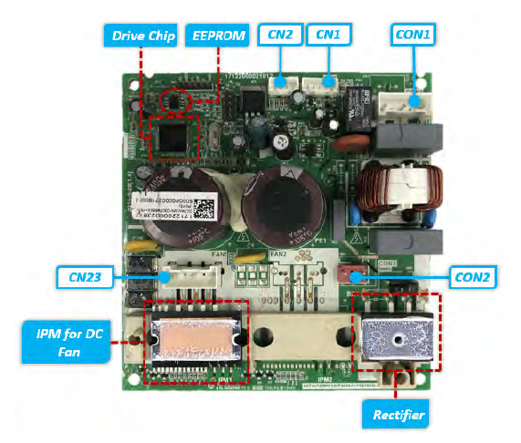
| Port | Description | Parameter | Remark |
| CON1 | PCB power input | 230 V/AC | - - - |
| CN1 | Main PCB communication | DC | - - - |
| CN2 | Test port | 5 V/DC | For debugging board |
| CN23 | UVW output for DC fan motor | - - - | - - - |
| CON2 | Reactor ports | - - - | - - - |
CN1 Communication with Main PCB (A6 Duct Unit)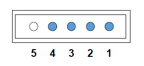
| No. | Signal | Voltage |
| 1 | Vcc | +15 V |
| 2 | GND | - - - |
| 3 | TXD | 0~6V |
| 4 | RXD | 0~15V |
| 5 | - - - | - - - |
Indoor DC Fan IPM Board (A7 Duct Unit)
- Turn on the power and confirm that the unit is in standby mode.
- On the DC motor driver board, measure the voltage at CN15. Then, on CN13, measure the voltage from pin 1 to pin 2 and from pin 3 to pin 2. If any reading is outside the range shown in the table below, the indoor main PCB is faulty and must be replaced.
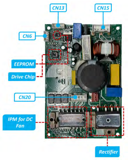
| Port | Description | Parameter | Remark |
| CN15 | PCB power input | 230 V/AC | L, N, and Earth |
| CN13 | Main PCB communication | DC | - - - |
| CN6 | Test port | 5 V/DC | For debugging board |
| CN20 | UVW output for DC fan motor | - - - | - - - |
| CN18L | Reactor ports | - - - | - - - |
CN13 Communication with Main PCB (A7 Duct Unit)
| No. | Signal | Voltage |
| 1 | Vcc | +15 V |
| 2 | GND | - - - |
| 3 | TXD | 0~6V |
| 4 | RXD | 0~15V |
| 5 | - - - | - - - |
Outdoor DC Fan Motor (Control Chip in Outdoor PCB)
- Disconnect the UVW connector.
- Measure the resistance between U and V, U and W, and V and W. If the three readings are not equal, the fan motor is faulty and must be replaced. If they are equal, the PCB is faulty and must be replaced.
Quantum Ultra Universal Flex (UYB-20)
Indoor DC Fan IPM Board
| Port | Description | Parameter | Remark |
| CON1 | PCB power input | 230 V/AC | - - - |
| CN1 | Main PCB communication | DC | - - - |
| CN2 | Test port | 5 V/DC | For debugging board |
| CN23 | UVW output for DC fan motor | - - - | - - - |
| CON2 | Reactor ports | - - - | - - - |
CN1 Communication with Main PCB (A6 Duct Unit)
| No. | Signal | Voltage |
| 1 | Vcc | +15 V |
| 2 | GND | - - - |
| 3 | TXD | 0~6V |
| 4 | RXD | 0~15V |
| 5 | - - - | - - - |
Outdoor DC Fan Motor (Control Chip in Outdoor PCB)
- Disconnect the UVW connector.
- Measure the resistance between U and V, U and W, and V and W. If the three readings are not equal, the fan motor is faulty and must be replaced. If they are equal, the PCB is faulty and must be replaced.