Wiring Diagrams for Vertex Ducted Central Split SystemsUpdated 18 days ago
Introduction
This article provides different wiring diagrams for Vertex Ducted Central Split (DYC-18) systems.
This article includes diagrams for the display board, outdoor unit mainboard, indoor unit control board, indoor and outdoor unit wiring, and thermostat wiring.
Display Board
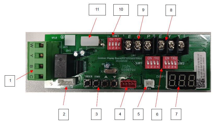
| No. | Port Definition | Description |
| 1 | 24V thermostat connection | Connected to the 24V thermostat |
| 2 | Communication port with the main board | Communicate with the main control board |
| 3 | Function buttons | View parameters, adjust parameters, select functions, etc. |
| 4 | Reserve ports | Reserve |
| 5 | T7 sensor port | Detect the outlet temperature of the condenser |
| 6 | SW1 & SW2 DIP switch | Adjust function parameters through the DIP switch |
| 7 | Display screen | Display parameter information or fault codes |
| 8 | Reserve ports | Reserve |
| 9 | PQE communication with the indoor unit | Only effective in RS-485 communication mode |
| 10 | SW3 DIP switch | Adjust function parameters through the DIP switch |
| 11 | USB debug port | Used to update the main control board program |
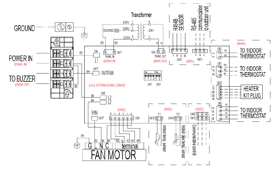
Indoor Unit Control Board
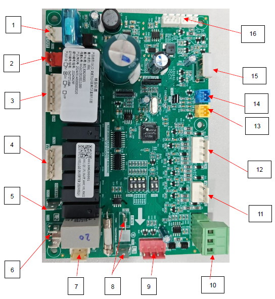
| No. | Port Definition |
| 1 | Transformer output (24V) |
| 2 | 24V thermostat power supply R, C |
| 3 | DC motor communicate port |
| 4 | Electric heater port (connected to the electric heater) |
| 5 | Power supply of the control board and DC motor N (L2) |
| 6 | Power supply (L2) |
| 7 | Transformer input (230V) |
| 8 | Power supply of the control board and DC motor L (L1) |
| 9 | Refrigerant leakage sensor |
| 10 | PQE indoor and outdoor communication |
| 11 | Electric heater port (to 24V thermostat) |
| 12 | 24V terminal connected to the 24V thermostat |
| 13 | T1 sensor |
| 14 | T2 sensor |
| 15 | Debug port |
| 16 | Smart controller port (Only active function in RS-485 communication mode) |
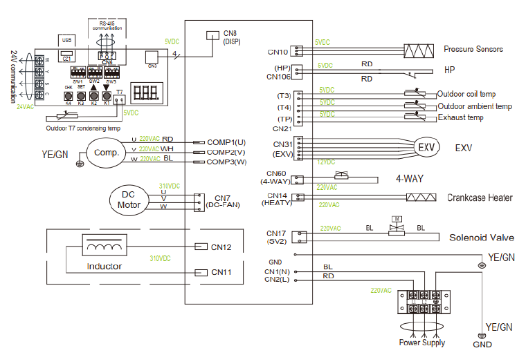
Outdoor Unit Mainboard
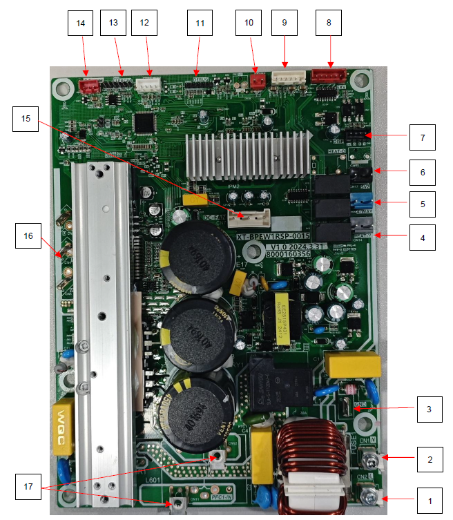
| No. | Port Definition |
| 1 | Power supply L (L1) |
| 2 | Power supply N (L2) |
| 3 | Ground wire |
| 4 | Crankshaft heating port |
| 5 | 4-way valve port |
| 6 | Solenoid valve port |
| 7 | Display board ports |
| 8 | Electronic expansion valve port |
| 9 | T3/T4/TP port |
| 10 | High-pressure switch port |
| 11 | DEGUG (reserved) |
| 12 | Test port (reserved) |
| 13 | E-part program burning port |
| 14 | Pressure sensor port |
| 15 | DC fan port |
| 16 | Compressor terminal U V W |
| 17 | Reactor port |
Indoor Unit Wiring Diagram
Outdoor Unit Wiring Diagram
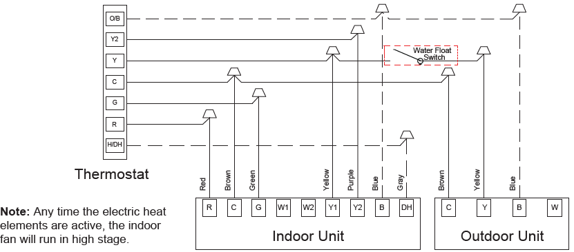
Thermostat Wiring Diagrams
The single-stage electric auxiliary heating is supported by a 2H thermostat, while the two-stage electric auxiliary heating is supported by a 3H thermostat.
The W signal of the outdoor unit is connected to the electric auxiliary heating or first-stage electric auxiliary heat.
- W1: The first stage of electric auxiliary heating installed in the indoor unit.
- W2: The second stage of electric auxiliary heating installed in the indoor unit.
The dotted line in the following thermostat wiring diagram indicates optional wiring (wiring for passive dehumidification and electric heating). For the wiring of the thermostat, refer to the user manual of the thermostat.
The reversing valve is energized in Heating mode and de-energized in Cooling mode. As factory default, the O/B terminal and reversing valve are set to be energized at the same time. Use DIP switch SW2-4 to achieve the opposite.
Wiring for 2H and 2C Thermostat
Wiring for 3H and 2C Thermostat
Wiring for 4H and 2C Thermostat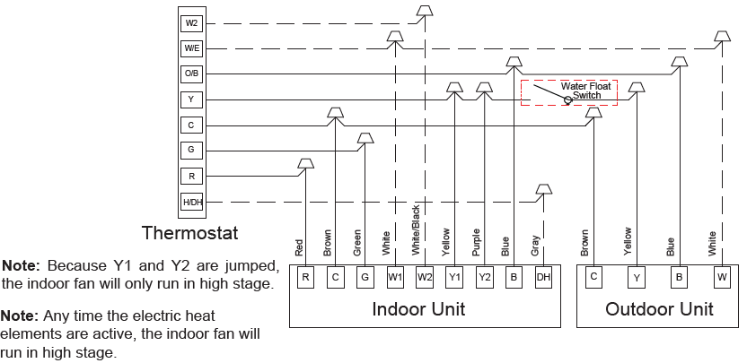
Wiring for 1H and 1C Thermostat
Wiring for 2H and 1C Thermostat
Wiring for 3H and 1C Thermostat