Structural Diagrams for Vertex Ducted Central Split SystemsUpdated 17 days ago
This article provides structural diagrams for Vertex Ducted Central Split (DYC-18) systems.
Indoor Units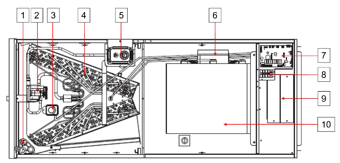
| No. | Name |
| 1 | Drain |
| 2 | TXV |
| 3 | Refrigerant leakage sensor |
| 4 | Indoor coil |
| 5 | Suction line / Liquid line |
| 6 | Fan motor |
| 7 | Control board |
| 8 | High voltage connection |
| 9 | Electric heater slot cover plate |
| 10 | Fan volute |
Outdoor Units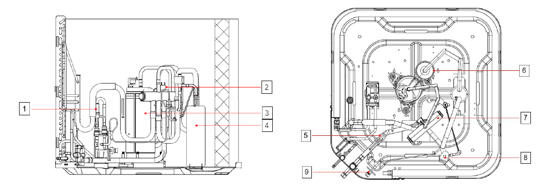
| No. | Name |
| 1 | EXV |
| 2 | High-pressure switch |
| 3 | Compressor |
| 4 | Accumulator |
| 5 | Pressure sensor |
| 6 | Oil separator |
| 7 | Reversing valve |
| 8 | Solenoid valve |
| 9 | Service valve |