Select the Installation Location for Ducted Central Split Outdoor UnitsUpdated 5 months ago
Introduction
This article explains how to select the ideal installation location for the outdoor unit of Vertex Ducted Central Split (DYC-18) systems.
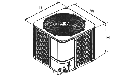
Unit Dimensions
| Unit Size | W x D x H |
| 24K/36K | 29-1/2" x 29-1/2" x 25" inches (749 x 749 x 635 mm) |
| 48K/56K | 29-1/2" x 29-1/2" x 32-7/8" inches (749 x 749 x 835 mm) |
Installation Precautions & Restrictions
Position Restrictions
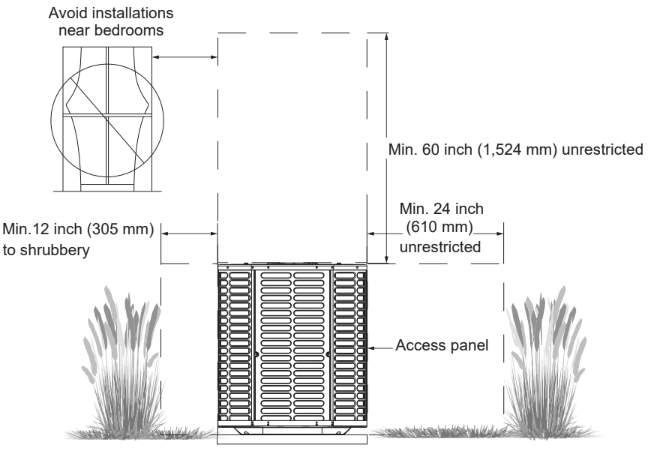
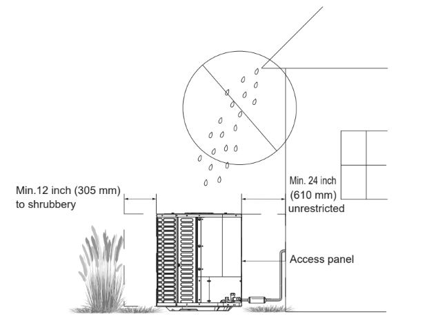
- Make sure that the discharge area is unrestricted. At least 5 feet (1.5 m) above the top of the unit.
- Do not position the outdoor unit near bedrooms, as the normal operating sound could be audible.
- Position the system in a way that leaves enough space for smooth airflow, wiring, refrigerant lines, and maintenance.
- Ensure there a minimum clearance of 12 inches (305 mm) on one side of the control board access panel, as well as a minimum clearance of 24 inches (610 mm) on the adjacent side of the control board access panel.
- Maintain a distance of 24 inches (610 mm) between the adjacent units.
- Make sure that lawn sprinklers, hoses, and waste water cannot spray directly on the outer panel of the unit for long periods of time.
- In coastal areas, install the unit on the side away from the waterfront.
- Avoid installing the unit in a location that is exposed to corrosive environments. This may shorten the service life of the unit, corrode metal parts, and negatively impact the performance of the unit. The following are examples of corrosive elements to avoid:
- Chloride
- Chlorine
- Compounds commonly found near seawater
- Fertilizers
- Fluorine
- Sodium
- Sodium hydroxide
- Sodium sulfate
- Sulfur
- Various chemical pollutants from industrial or manufacturing plants
Cold Climates
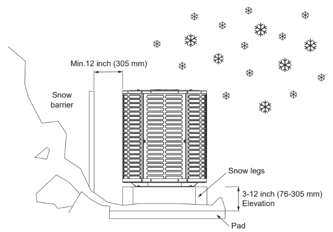
- Select a location where water, snow, or ice cannot fall directly on the system from the roof or overhangs. Precautions must be taken for units installed in areas with snow and long-term temperatures below the freezing point.
- In snowy areas, raise the unit by 3-12 inches (76-305 mm). This extra height will allow the snow and ice that melts during defrosting cycles to discharge before freezing. Ensure that the drain hole on the unit chassis is not blocked, otherwise it might limit the defrosting water discharge.
- If possible, avoid locations that are prone to snow. If this not possible, install a snow barrier around the unit to prevent snow from accumulating on the side of the unit.
Restrictions for Refrigerant Pipelines
| Refrigerant Line | Capacity (Kbtu/h) | ||||
| 24K | 36K | 48K | 56K | ||
| Liquid Suction | inches | 3/8-3/4 | 3/8-3/4 | 3/8-7/8 | 3/8-7/8 |
| Max. Refrigerant | feet | 100 | |||
| Line Length* | |||||
| Max. Elevation* | feet | 50 | |||
| Vertical Lift* | |||||
*It is recommended to adopt standard pipeline sizes.
- Maximum equivalent length of the pipeline = 100 feet (30.5 m)
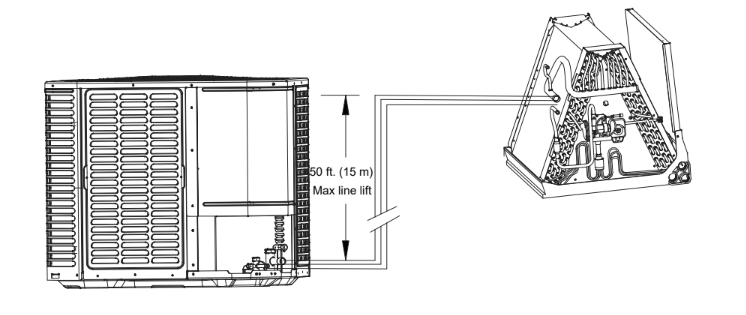
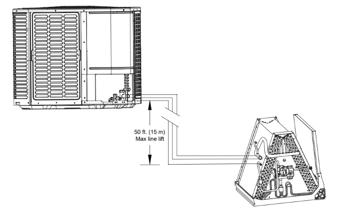
- Maximum vertical equivalent length = 50 feet (15 m).
- If the suction line exceeds 65 feet (20 m), do not use a suction line larger than recommended.
Long Line Installation Precautions
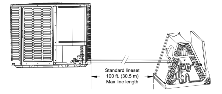
- The length of the connecting line from the outdoor unit to the indoor unit cannot exceed 100 feet (30.5 m).
- If all the long lines are in a horizontal position, no additional measures are required.
- If there is a vertical height difference in the long lines, install them according to the following requirements:
- When the vertical height difference of the indoor and outdoor units is less than 16.5 feet (5 m), no additional measurements are required.
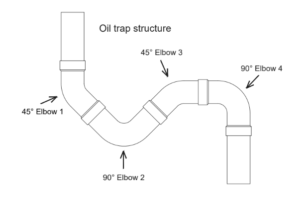
- When the vertical height difference is more than 16.5 feet (5) but less than 33 feet (10 m), add an oil return trap in the middle of the height difference.
.png)
- When the vertical height difference is more than 33 feet (10 m) but less than 50 feet (15 m), add two oil return traps at an equal distance in the height difference.
- The vertical height difference between the indoor and outdoor units cannot exceed 50 feet (15 m). The following is the connection method of the oil return trap:
Installation Notes
- Fences or shrubs can provide additional shielding protection for the unit. Be sure to maintain the minimum clearances for the unit.
- When installing the outdoor unit on the roof, ensure that the roof can support the weight of the unit. Choose an appropriate isolation position to prevent sound or vibration from being transmitted to the building structure.