Understand the DIP Switches for Vertex Ducted Central Split SystemsUpdated 5 months ago
Introduction
This article explains the layouts for the DIP switches of the Vertex Ducted Central Split (DYC-18) systems.
Buttons in the Up position indicate they're on.
DIP Switch on the Display Board
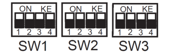
| SW1-1 | On | RS-485 communication mode |
| Off | 24V control (factory default) | |
| SW1-2 | On | Display unit: °C and Mpa |
| Off | Display unit: °F and PSI (factory default) | |
| SW1-3 | On | System operation mode: Cooling only |
| Off | System operation mode: Heat pump (factory default) | |
| SW1-4 | On | USB upgrade |
| Off | Reserved (factory default) | |
| SW2-1 | On | Fix timed defrost |
| Off | Auto defrost (factory default) | |
| SW2-2 | On | Timer 30 minutes |
| Off | Timer 60 minutes (factory default) | |
| SW2-3 | On | Powerful defrosting |
| Off | Normal (factory default) | |
| SW2-4 | On | O/B terminal energized in Cooling mode |
| Off | O/B terminal energized in Heating mode (factory default) | |
| SW3-3 | On | Accelerated cooling |
| Off | Normal cooling (factory default) | |
| SW3-4 | On | Accelerated heating |
| Off | Normal heating (factory default) |
| Mode | SW3-1 | ||
| On | Off | ||
| SW3-2 | On | 5 Ton | 3 Ton |
| Off | 4 Ton | 2 Ton | |
DIP Switch on the Indoor Control Board
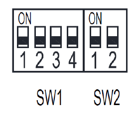
| SW1-1 | RS-485 communication mode |
| 24V thermostat control | |
| SW1-2 | Heating fan delay 90 seconds |
| Anti-cooling fan delay | |
| SW1-3 | T1 temperature sensor from the thermostat |
| T1 temperature sensor from the AHU return | |
| SW1-4 | USB port software update |
| Reserved |
| SW2-1 | SW2-2 | High Speed Taps | Low Speed Taps |
| Off | Off | 3 --- Medium | 1 --- Low |
| On | Off | 4 --- Medium High | 2 --- Medium Low |
| Off | On | 4 --- Medium High | 3 --- Medium |
| On | On | 5 --- High | 4 --- Medium High |